Conceptual design: the entity-relationship model
Entities, attributes and identifiers, relationships and cardinalities, generalisations, the example of a degree course registry, translation into tables, many-to-many relationships with proof.
Before creating tables one must understand what is to be represented: which objects, which links, which rules. Conceptual design produces a schema independent of the system that will host it, understandable even to non-specialists. The most widely used model is the entity-relationship (E-R) model, proposed by Peter Chen in 1976. In this lesson we look at entities, attributes and identifiers, relationships and their cardinalities, generalisations, a complete example, and the rules for translating the schema into tables, with the proof of why many-to-many relationships require a table of their own.
Entities and attributes
An entity is a class of objects with independent existence and common properties: students, courses, lecturers. Each concrete object is an instance. The properties are the attributes: student number, name, date of birth. An identifier is a set of attributes that distinguishes each instance from all others: for the student, the student number. In diagrams entities are drawn as rectangles, attributes as small circles, filled if they belong to the identifier.
Relationships and cardinalities
A relationship (or association) is a link between entities: a student takes an exam for a course. Relationships too can have attributes: the mark and the date belong to the link between that student and that course, not to either one.
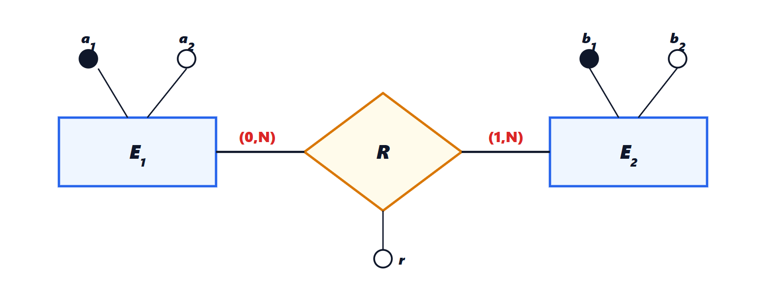
Cardinalities say how many times an instance takes part in the relationship, at minimum and at maximum. (0,N) for the student in the relationship with courses means that they may not have taken any exams yet and may take many; (1,1) for a car in the relationship with its owner means it has exactly one. Looking at the maxima, binary relationships are classified as one-to-one, one-to-many and many-to-many. Cardinalities are rules of the real world, and must be asked of those who know it: “can an order contain products from several suppliers?” changes the schema.
Generalisations
When some entities are special cases of another, a generalisation is used: lecturers and students are persons, with common attributes (name, tax code) inherited from the parent entity and attributes of their own (the student number for the student, the field for the lecturer). A generalisation can be total (every person is a lecturer or a student) or partial, disjoint (one cannot be both) or overlapping.
An example
The registry of a degree course. Entities: Student (student number, first name, surname, date of birth), Course (code, title, credits), Lecturer (code, first name, surname). Relationships: Exam between Student (0,N) and Course (0,N), with attributes mark and date; Teaching between Lecturer (0,N) and Course (1,1), because every course has exactly one lecturer in charge. The rules the schema does not express, such as “the mark is between 18 and 30” or “a student cannot take an exam they have already passed”, are written separately as integrity constraints.
From concept to tables
Logical design translates the E-R schema into tables of the relational model (lesson on the relational model). The main rules:
- every entity becomes a table, with its identifier as primary key;
- a one-to-many relationship does not become a table: a foreign key referring to the key of the other side is added to the table on the “many” side. Course receives the column with the code of its lecturer;
- a one-to-one relationship is translated in the same way, placing the foreign key on the side with mandatory participation;
- a many-to-many relationship becomes a table of its own, with the keys of the two entities and the attributes of the relationship: Exam(student_number, course_code, mark, date);
- generalisations are translated with a single table with a field indicating the type, or with separate tables for the child entities.
Theorem. A many-to-many relationship cannot be represented with a foreign key in one of the two entity tables without repeating data or breaking the one-value-per-cell rule.
Proof. Suppose a column with the course code is put in Student. A student linked to two courses would require two values in the same cell, forbidden in the relational model (every cell holds an atomic value), or two rows for the same student, which would repeat first name, surname and date of birth and make the student number lose its role as key. The same happens putting the column in Course, for a course with several students. Since in a many-to-many relationship both sides can have several partners, neither placement avoids the problem: a table is needed in which each row represents a single link. ∎
Conceptual design done well avoids most of the redundancy problems that normalisation (dedicated lesson) would otherwise have to correct.