The datapath and the control unit
Components of a RISC-V datapath, execution of add, lw, sw and beq, control signals and why single-cycle is slow.
Inside the processor, instructions are executed by a datapath: registers, memories, ALU, multiplexers and the connections between them. The control unit decides, instruction by instruction, which routes to open. In this lesson we build the datapath of a simple RISC-V processor that executes each instruction in a single clock cycle, and we see why this solution is slow.
The components
- The program counter (PC), a 32-bit register.
- The instruction memory (IMEM): given an address, it returns the instruction.
- The register file (REG): 32 registers, with two read ports (for the two operands) and one write port, all usable in the same cycle.
- The immediate generator (IMM): it extracts the constant from the instruction fields and sign-extends it to 32 bits.
- The ALU, with a control input selecting the operation.
- The data memory (DMEM), for loads and stores.
- An adder computing PC + 4, the address of the next instruction.
- A few multiplexers, which choose between two possible sources of a value.
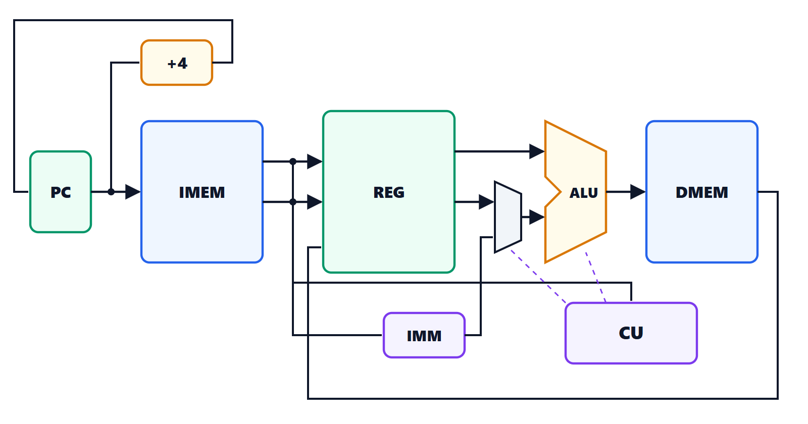
The path of an instruction
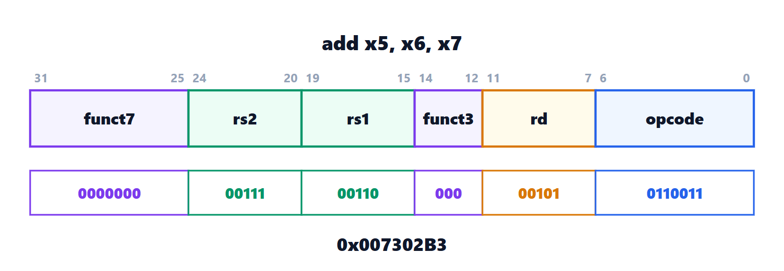
add x5, x6, x7
- The PC addresses the instruction memory.
- The fields rs1 = 6 and rs2 = 7 select two registers, read in parallel.
- The multiplexer in front of the ALU picks the second register (not the constant); the ALU adds.
- The data memory is not used; another multiplexer picks the ALU result, which is written into register rd = 5.
- The PC becomes PC + 4.
lw x5, 8(x6): the ALU adds register x6 and the constant 8 (this time the multiplexer picks the constant) and computes the address; the data memory reads the word; the final multiplexer picks the data read, which goes into x5.
sw x5, 8(x6): the same address calculation, then the memory writes the value of x5; no register is written.
beq x5, x6, label: the ALU subtracts the two registers and signals whether the result is zero; in that case the PC receives PC plus the constant (the branch offset) instead of PC + 4. This needs a second adder and another multiplexer on the PC.
The control unit
The control unit reads the opcode (and funct3, funct7) and produces the control signals: which operation the ALU performs, whether the second operand is a register or the constant, whether a register is written, whether memory reads or writes, where the data to write comes from, whether the PC branches. In a single-cycle processor it is a simple combinational network, a table mapping each instruction type to signal values:
| Instruction | ALU | Second operand | Writes register | Memory | Data written |
|---|---|---|---|---|---|
| add | add | register | yes | none | ALU |
| addi | add | constant | yes | none | ALU |
| lw | add | constant | yes | read | memory |
| sw | add | constant | no | write | |
| beq | subtract | register | no | none |
Why single-cycle is slow
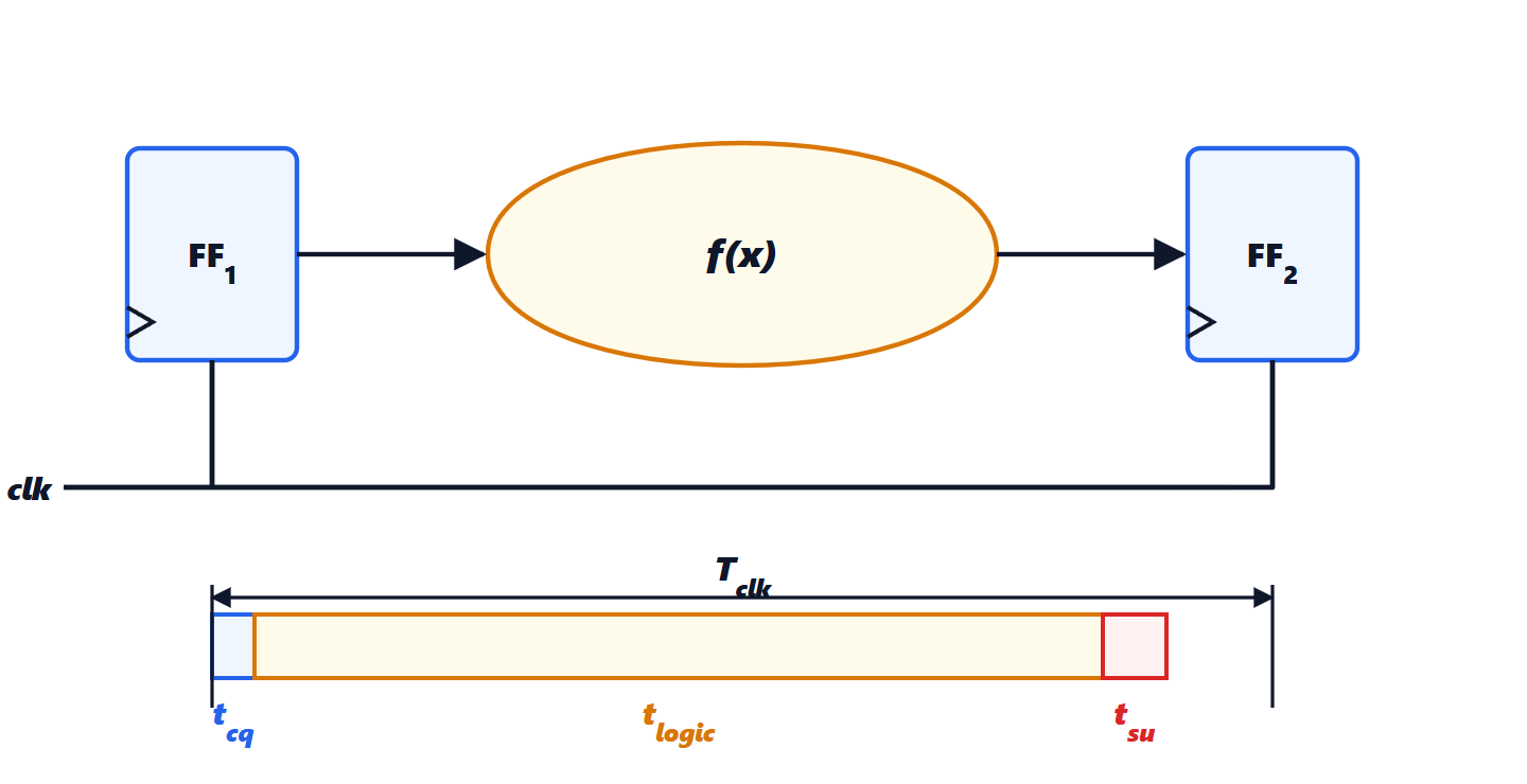
In one clock cycle the longest instruction must complete, the load, which goes in sequence through instruction memory, register file, ALU, data memory and back to the register file. Suppose delays of 200 ps for each memory, 100 ps for register read, 150 ps for the ALU, 50 ps for write-back: the cycle must last at least  ps, that is about 1.4 GHz. An add, which does not use the data memory, would finish in 500 ps, but must still wait for the end of the cycle.
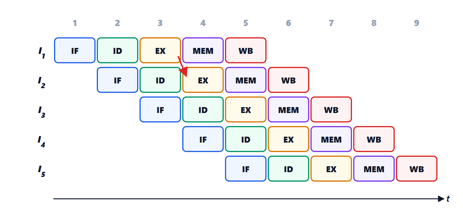
There are two solutions. Multicycle splits execution into shorter steps and uses only the ones each instruction needs. The pipeline, which we will see in the next lesson, splits the datapath into stages and makes them work simultaneously on different instructions: it is the solution of every modern processor, from microcontrollers to servers.