Combinational logic: multiplexers, decoders, comparators and hazards
The multiplexer and its universality, demultiplexers, decoders and priority encoders, comparators, static hazards with an example and the consensus term, description in Verilog.
A combinational network is a circuit whose output depends only on its inputs at that instant, with no memory. Some combinational blocks occur so often that they are standard components: multiplexers, decoders, encoders, adders, comparators. In this lesson we look at them and discover a problem that truth tables hide: spurious transitions caused by delays.
The multiplexer
A  :1 multiplexer (MUX) picks one of inputs and routes it to the output, according to
 select signals.
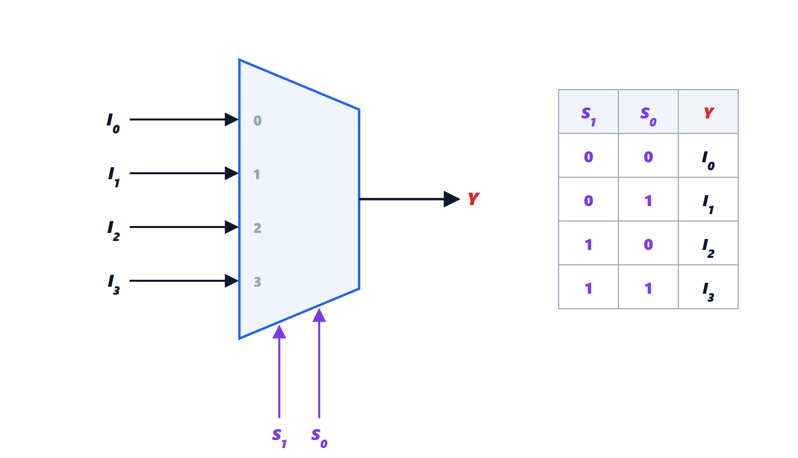
For the 4:1:

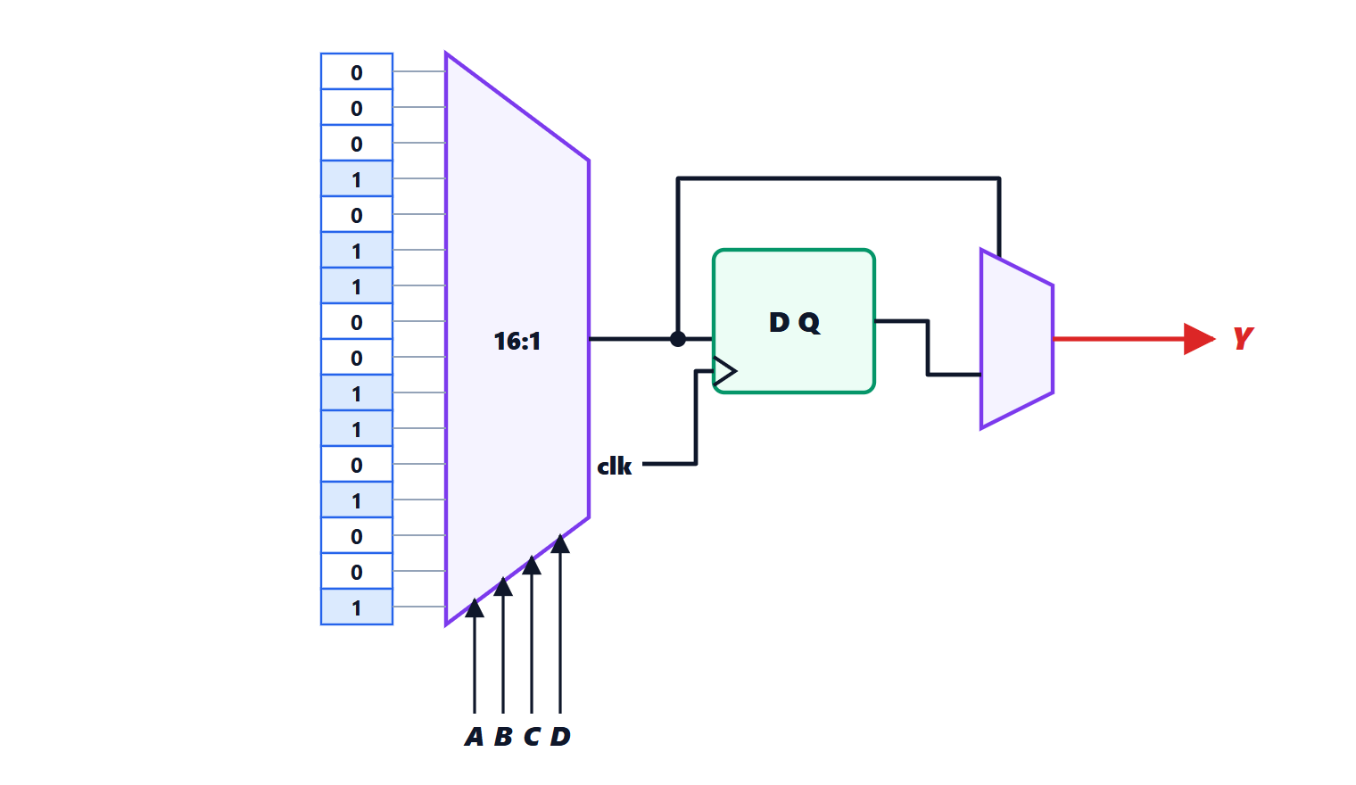
Each term is active for a single combination of the selects. The multiplexer is a universal block: tying the data inputs to constants 0 and 1, a MUX with selects implements any function of variables, just by writing the truth table column on the inputs. This is exactly how the look-up tables (LUTs) of FPGAs work.
The demultiplexer does the reverse: it routes one input to one of outputs.
Decoders and encoders
- An -to- decoder activates just one of its outputs, the one whose number is given by the inputs: each output is a minterm. It is used to select one of many devices (the right memory chip based on the address, the row of a memory array) and to drive seven-segment displays.
- An encoder does the inverse: given which of lines is active, it produces its number. The priority encoder also handles several active lines, returning the most important one: it is the heart of interrupt controllers.
Adders and comparators
The full adder and the ripple-carry and carry-lookahead adders are in the Computer Architecture lesson on arithmetic. An equality comparator between two -bit words compares the bits in pairs with XNOR gates and ANDs the results:  if all bits match. A magnitude comparator (
 ) is obtained with a subtraction and a check of the sign or carry.
Spurious transitions
The truth table describes the network in steady state, but gates have delays, and different paths from input to output can have different delays.
Example.  , with
 : the function is always 1, whatever
 . When goes from 1 to 0, the term
 goes to 0 immediately, while
 goes to 1 only after the delay of the inverter producing
 . For an instant both terms are 0, and the output has a brief pulse to 0 (a glitch). This is a static hazard.
On the Karnaugh map the hazard is easy to see: the two groups and are adjacent but do not overlap, and the move from one to the other is not covered. Adding the consensus term  , which covers the transition, removes the hazard:
 is logically identical but glitch-free.
In synchronous circuits (next lessons) combinational glitches are usually harmless, because flip-flops read the outputs only on the clock edge, once they have settled. They are dangerous, however, when the combinational output directly drives something edge-sensitive: a clock, an asynchronous reset input, an interrupt. Rule of thumb: never use the output of a combinational network as a clock.
Networks in practice
Today almost nobody draws combinational networks gate by gate. The behaviour is described in a hardware description language, for example assign y = sel[1] ? (sel[0] ? i3 : i2) : (sel[0] ? i1 : i0); in Verilog, and the synthesis tool chooses the implementation with the cells of the available technology, also checking the delays. Understanding the basic blocks is still essential to read the results, estimate area and delay and find bugs.