Latches and flip-flops: memory, setup, hold and metastability
The NOR SR latch, the transparent D latch, the master-slave D flip-flop, setup and hold times, metastability with the MTBF calculation, and synchronisers.
A combinational network forgets everything as soon as its inputs change. To count, remember a state, build registers and processors, memory elements are needed: circuits that hold a bit until we decide to change it. In this lesson we see how feedback creates memory in the SR latch, the D latch, the edge-triggered D flip-flop, its timing constraints and the phenomenon of metastability.
The SR latch
Two NOR gates connected in a loop: the output of each is an input of the other.
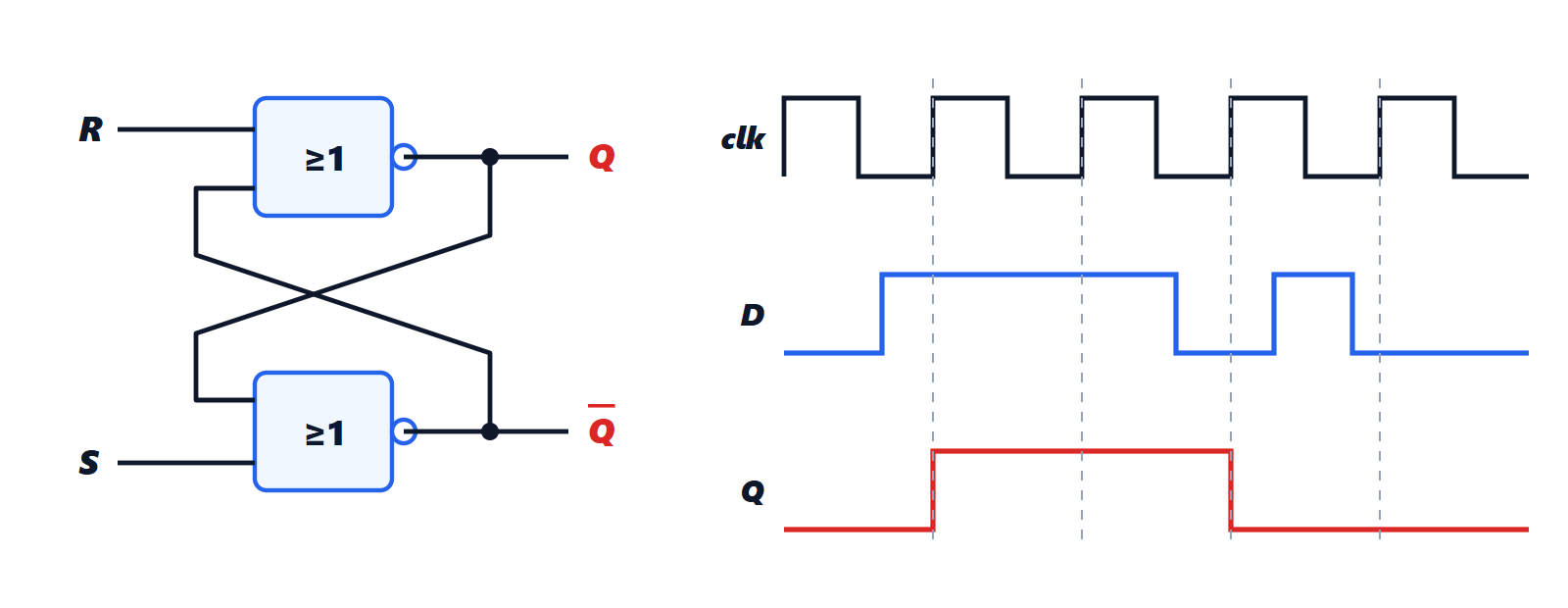
Operation.
 : the lower gate has an input at 1, so
 ; the upper gate has both inputs at 0, so
 . The latch is set.
 : by symmetry
 : the latch is reset.
 : each gate acts as an inverter of the other. The combinations
 and
 are both stable, and the latch holds whichever it was in. This is memory.
 : both outputs at 0, and when the two inputs return to 0 together the final state is unpredictable. It is the forbidden combination.
The principle is deep: two inverters in a loop have two stable equilibrium states, and the state they are in is the stored information. An SRAM memory cell is exactly this, plus two transistors to read and write it.
The D latch
To remove the forbidden combination and control when data is stored: a single data input  and an enable input
 . With
 the latch is transparent:
 follows . With
 the latch is closed and holds the last value. The problem with transparency is that, while stays at 1, every change of reaches the output, and in a circuit with feedback the signal could go round several times in the same period.
The D flip-flop
The D flip-flop changes state only at the instant of the clock’s rising edge: takes the value has at that moment and holds it for the whole period, whatever does meanwhile. It is built from two D latches in cascade (master-slave) enabled by opposite clock phases: with the clock low the first is transparent and follows , the second is closed; on the rising edge the first closes, freezing the value, and the second opens and passes it to the output. There is never a transparent path from to .
The D flip-flop is the memory element of almost all synchronous digital circuits. The other types (JK, T) are derived from it with a little logic: for example a T flip-flop, which toggles its state on every edge, is a D with  , that is a divide-by-two frequency divider.
Timing constraints
For the flip-flop to capture the data correctly, must be stable:
- for a time
 before the edge (the setup time);
- for a time
 after the edge (the hold time).
After the edge, the output changes with a delay  (clock to output). These three parameters, tens of picoseconds in modern integrated circuits, set the maximum frequency of a synchronous circuit, as we will see in the lesson on timing.
Metastability
What happens if changes right inside the setup and hold window? The internal latch can stop at an unstable equilibrium point halfway between 0 and 1, like a ball on top of a hill, and stay there for an unpredictable time before falling one way or the other. This is metastability.
It cannot be avoided when sampling an asynchronous signal (a push-button, data arriving from another device with a different clock), because sooner or later it will change at the wrong moment. It can, however, be made extremely unlikely. The probability that the metastable state lasts longer than a time  decreases as
 , with
 a flip-flop constant of tens of picoseconds, and the mean time between failures is
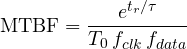
Example. With  ps,
 ps, a 100 MHz clock and data changing at 1 MHz: allowing
 ns to resolve, the MTBF is about
 s, less than three days; with
 ns it becomes
 s, almost four million years. The exponential makes every extra nanosecond enormously effective.
Hence the universal rule: an asynchronous signal goes through a synchroniser, two (or three) flip-flops in cascade on the same clock, before being used. The first may go metastable, but it has a whole period to resolve before the second reads it.