Sequential logic: registers, counters and finite state machines
Registers and shift registers, LFSRs, synchronous and asynchronous counters, Moore and Mealy machines, complete design of a sequence recogniser, encodings and reset.
Flip-flops are used to build sequential networks: circuits whose output depends not only on the current inputs but on past history, summarised in a state. Registers, counters, protocol controllers, a processor’s control unit are all synchronous sequential networks. In this lesson we cover registers and counters and the general method for designing a finite state machine, with a complete example.
Registers and shift registers
An  -bit register is made of D flip-flops on the same clock: at each edge it stores a word. Connecting each flip-flop’s output to the next one’s input gives a shift register: at each edge the bits move one position. It converts data from parallel to serial and back (it is the heart of UART, SPI and all serial links), delays a signal by a precise number of cycles, and generates pseudo-random sequences (with XOR feedback, the LFSR, used for GPS codes and for chip testing).
Counters
An -bit synchronous binary counter is a register whose input is the current value plus 1: it counts from 0 to  and starts again. The least significant bit changes at every edge, the next every two, and so on: each bit halves the frequency. A modulo-N counter resets when it reaches
 : counting the seconds of a clock needs 6 bits (
 ).
Asynchronous (ripple) counters, in which each flip-flop is clocked by the previous one’s output, use less logic but the bits do not change together: for an instant the counter passes through wrong values. Modern designs almost always use synchronous counters.
Finite state machines
A finite state machine (FSM) is described by:
- a finite set of states, stored in a register;
- a next-state function, which computes the next state from the current state and the inputs (combinational logic);
- an output function.
In a Moore machine the output depends only on the state; in a Mealy machine it also depends on the inputs. Moore machines are easier to verify and have outputs stable for the whole cycle; Mealy machines react one cycle earlier and often need fewer states.
A complete example: recognising the sequence 101
We want a circuit with a serial input  , one bit per clock cycle, and an output
 that is 1 when the last three bits received are 1, 0, 1 (overlapping too: in 10101 the sequence appears twice).
1. The state diagram. Each state remembers how much of the sequence has already arrived:
 : nothing useful;
 : the last bit was 1;
 : the last two were 1, 0;
 : the last three were 1, 0, 1, output 1 (Moore machine).
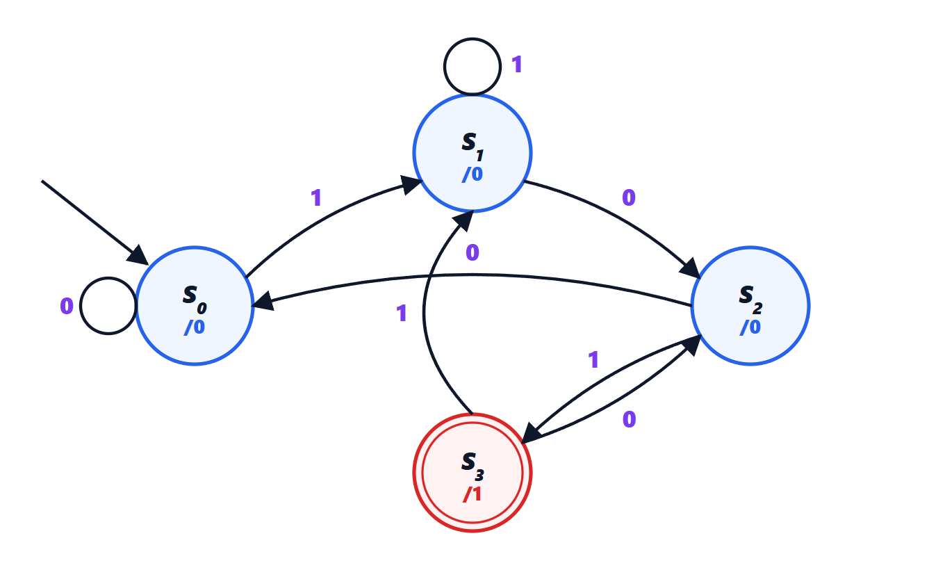
The transitions are found by asking, for each state and each input, which is the longest prefix of the sequence that matches the end of what has been received. For example in (last bits 101) a 0 gives …1010, which ends with 10: we go to , not .
2. The state table.
| State |  |  | |
|---|---|---|---|
| | | 0 |
| | | 0 |
| | | 0 |
| | | 1 |
3. Encoding. Four states need 2 flip-flops. With the binary encoding  ,
 ,
 ,
 (bits
 ), the next-state functions follow from the table and are simplified with Karnaugh maps:

Check row by row: for example from ( ) with :
 ,
 , that is
 , correct. (Here
 has a simple meaning:
 remembers the last bit received.)
4. The circuit. Two D flip-flops, the gates implementing  and
 , and one AND gate for the output.
Other encodings are possible: one-hot uses one flip-flop per state (4 here), with simpler, faster logic; it is the usual choice in FPGAs, where flip-flops are plentiful. Synthesis tools choose the encoding themselves, starting from the description in a hardware description language.
Reset
Every state machine must start from a known state: at power-up the flip-flop contents are random. A reset signal brings the state register to the initial state. If the reset is asynchronous, its release must still be synchronised with the clock (with the same synchroniser seen for metastability), otherwise different flip-flops might leave reset in different cycles and the machine would start from an unexpected state.