Sequences with GRAFCET and SFC
Steps, transitions and actions, evolution rules, a drilling station, translation into code with a single active step proved, divergences, interlocks and operating modes.
Much of industrial automation is sequential logic: clamp the part, drill, withdraw the tool, unclamp, start again. Describing a sequence with scattered Boolean equations is a source of errors; the sequential function chart makes it readable like a recipe. In this lesson we look at GRAFCET and SFC, the evolution rules, an example of a drilling station, the translation into code with the proof that it keeps a single step active, branches and interlocks.
Steps, transitions, actions
GRAFCET (IEC 60848) and its programming equivalent, SFC (sequential function chart, one of the IEC 61131-3 languages), describe a sequence with:
- steps: the states of the machine, shown as numbered squares; the initial step has a double border. Each step is active or inactive;
- actions associated with the steps: the outputs commanded while the step is active;
- transitions between steps, shown as bars, with a receptivity: the logical condition (sensors, push buttons, timers) that allows them to be crossed.
Evolution rules
- At the start the initial steps are active.
- A transition is enabled if all the immediately preceding steps are active; it is fired if it is enabled and its receptivity is true.
- Firing a transition deactivates the preceding steps and activates the following ones.
- Transitions that can be fired at the same instant are fired simultaneously.
- If a step must be both activated and deactivated, it stays active.
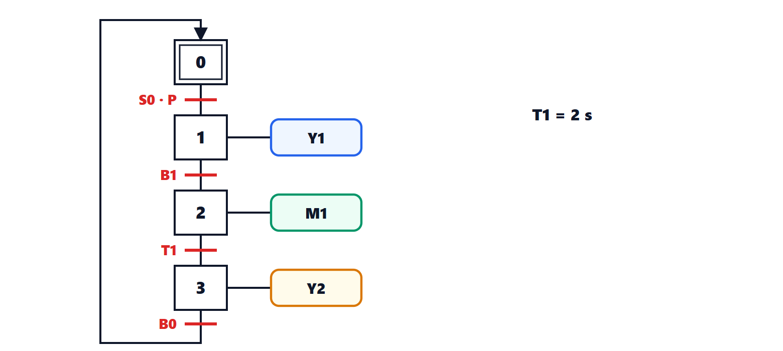
Example. In the drilling station, in step 0 the machine waits for start with the part present; in step 1 cylinder Y1 clamps the part until sensor B1 confirms clamping; in step 2 motor M1 drills for 2 s (timer T1 starts when the step becomes active); in step 3 output Y2 brings the spindle back until sensor B0, and it returns to step 0. Anyone, even the maintenance technician who did not write the program, reads the sequence and understands at which step the machine stopped.
From chart to code
Many PLCs execute SFC directly; otherwise it is translated. A Boolean variable  is associated with each step
 . For each transition from step to step
 with receptivity
 :

and the outputs are computed from the steps: Y1 =  , M1 =
 , Y2 =
 .
Theorem. In a linear sequence closed in a loop, starting with only the initial step active and evaluating at each cycle all transitions on the state at the start of the cycle, exactly one step is always active.
Proof. By induction on cycles. At the start a single step is active. Suppose that at the start of a cycle only step is active. In a linear sequence the only enabled transition is the one leaving , because every other transition has an inactive step as its predecessor. If its receptivity is false nothing changes; if it is true, is reset and only the next step is activated. In both cases at the end of the cycle a single step is active. ∎
The condition “on the state at the start of the cycle” is not a detail. If the program evaluated the transitions in order and each saw the changes made by the previous ones, a step just activated could be left in the same cycle, and with receptivities already true the sequence would “slide” through several steps at once, skipping actions. To avoid this, all fireable transitions are computed first and then the steps are updated; or the transitions are written in reverse order. The same sequence is written in structured text with a CASE statement on the step number (lesson on PLC programming).
Branches
- Alternative divergence (OR): several transitions leave a step, and one branch is chosen, for example according to the part type. The receptivities must be mutually exclusive, otherwise two branches would be activated.
- Simultaneous divergence (AND, double line): once the transition is fired, several steps are activated together, for example two stations working in parallel; the simultaneous convergence waits until all branches have finished. Here the previous theorem no longer holds: more than one step is active, and the count returns to one at the convergence.
Interlocks and operating modes
The sequence describes normal operation, but a real machine also has:
- interlocks: conditions preventing a dangerous or damaging action regardless of the step (do not drill if the part is not clamped, do not open two incompatible valves). They are written as additional conditions on the outputs, not only on the transitions;
- modes manual, automatic, single cycle, and the handling of stops and restart after an emergency, which often require more code than the sequence itself. The GEMMA guide organises these modes in a standard chart;
- time monitoring: if a step lasts much longer than expected (sensor B1 never arrives), an alarm is raised indicating the step and the expected sensor, which halves fault-finding times.
Safety functions for people, such as the emergency stop, are not entrusted to the standard PLC sequence: they require certified components and logic (lesson on functional safety).