Programming PLCs: IEC 61131-3, response time and function blocks
The five languages, worst-case response time proved with an example, tasks and priorities, a function block in structured text, good design and testing practices.
The software of a modern plant can have hundreds of thousands of lines and remain in service for decades, modified by different people. The IEC 61131-3 standard fixes the PLC languages, but writing a good program also needs the rules of software engineering. In this lesson we look at the languages of the standard, the worst-case PLC response time with its proof and an example, tasks and priorities, function blocks with an example in structured text, and good design and testing practices.
The languages
IEC 61131-3 defines five languages, which can coexist in the same project:
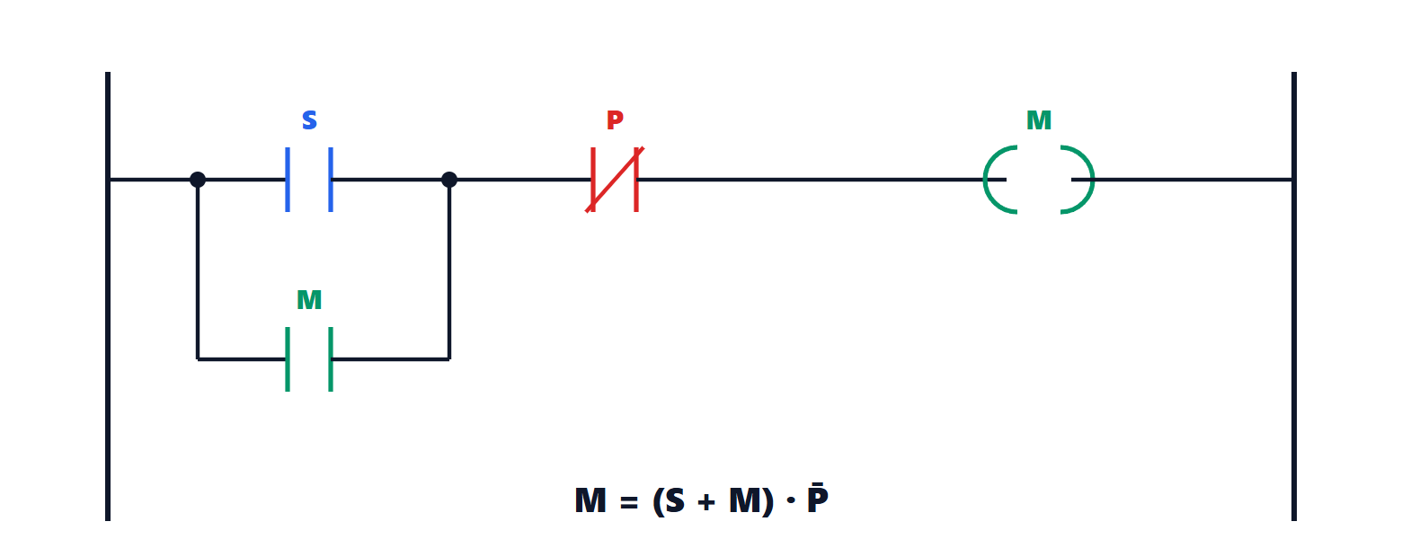
- LD (ladder diagram): the relay schematic, readable by electricians, suited to simple Boolean logic (Process Control lesson on PLCs);
- FBD (function block diagram): blocks connected by wires, natural for control loops;
- ST (structured text): a textual language similar to Pascal, with expressions, loops and structures; the best suited to algorithms, calculations and state machines;
- SFC: sequences (lesson on sequences);
- IL (instruction list), similar to assembly, declared obsolete in the third edition of the standard.
The third edition (2013) added object-oriented programming: methods, interfaces, inheritance of function blocks.
The cycle and response time
A PLC runs in a cycle: it reads all inputs into a memory image, executes the program on that image, writes all outputs. The cycle lasts  , from less than a millisecond to a few tens.
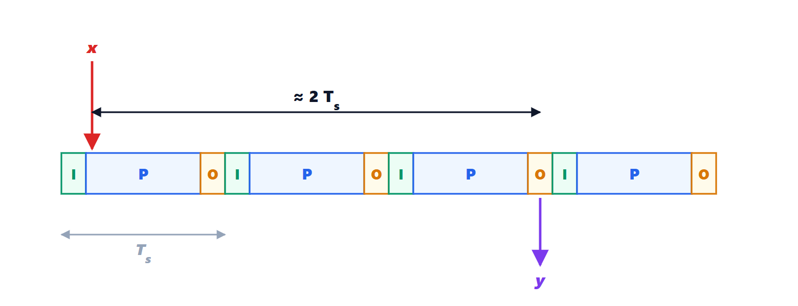
Theorem. The time between the change of an input and the change of the output depending on it is at most about  , plus the input filter and output delays.
Proof. In the worst case the input changes just after the inputs are read: the program of that cycle still uses the old value, and the new one is read at the start of the next cycle, after almost . The program processes it and the output is written at the end of that cycle, after another . In total almost , to which the input filter (against bounce and noise) and the output switching time are added. ∎
Example. A 10 ms cycle, 3 ms input filter, relay output of 10 ms: up to  ms. An input pulse shorter than one cycle may even never be seen. For fast events, interrupt inputs, hardware high-speed counters or tasks with a shorter cycle are used.
Tasks and priorities
The program is divided into tasks with different periods and priorities: a fast task (1-2 ms) for critical functions, a normal one (10-20 ms) for logic, a slow one (100 ms or more) for service functions, plus event-triggered tasks. It is the same fixed-priority scheduling as in real-time systems (Operating Systems lesson on real-time systems): the load of fast tasks must be kept low, and the PLC monitors the cycle time with a watchdog that brings the outputs to a safe state if it is exceeded.
Function blocks
A function block (FB) is a module with inputs, outputs and internal memory; as many instances are created as there are identical machines. The standard provides some standard ones, such as timers (TON, TOF, TP) and edge detectors (R_TRIG). An example in structured text: the control of a pump as a state machine, with thermal protection and reset.
FUNCTION_BLOCK FB_Pump
VAR_INPUT
    Start, Stop, Thermal : BOOL;      (* Thermal = thermal relay tripped *)
END_VAR
VAR_OUTPUT
    Contactor, Alarm : BOOL;
END_VAR
VAR
    State : INT := 0;                 (* 0 stopped, 1 running, 2 fault *)
END_VAR

CASE State OF
    0:  Contactor := FALSE;
        IF Start AND NOT Stop AND NOT Thermal THEN State := 1; END_IF;
    1:  Contactor := TRUE;
        IF Thermal THEN State := 2;
        ELSIF Stop THEN State := 0; END_IF;
    2:  Contactor := FALSE;
        Alarm := TRUE;
        IF NOT Thermal AND Stop THEN      (* reset: fault cleared and confirmed *)
            Alarm := FALSE; State := 0;
        END_IF;
END_CASE;
END_FUNCTION_BLOCK
Each state declares its outputs explicitly; the fault takes precedence over stop; the reset requires the cause to have cleared and an operator action, so the pump does not restart by itself. Ten pumps are ten instances of the same block, tested once.
Good practices
- Structure: small blocks with a clear purpose; no global variables used everywhere; meaningful names and a shared convention.
- Separation between process logic, mode handling, alarms and the operator interface.
- Libraries of tested blocks for recurring components (motors, valves, controllers), which make the code uniform and reduce errors.
- Version control of the code, with the history of changes: modern environments export projects in a textual format (PLCopen XML) precisely for this.
- Testing: block tests on a simulator, automatic regression tests, and virtual commissioning with a plant model (lesson on commissioning).
- Comments that explain why, not how.
- For motion control, the PLCopen specifications standardise the blocks (MC_MoveAbsolute and similar) across manufacturers (lesson on drives).