The PLC: scan cycle, IEC 61131-3 languages and sequences
Structure of a PLC, the scan cycle and the response time proved, ladder, FBD, ST and SFC languages, start-stop with seal-in, fail-safe design, timers and sequences, safety PLCs, the automation pyramid.
Alongside the continuous regulation of temperatures and flows, every plant has a logical and sequential part: starting and stopping motors, opening valves in a certain order, counting parts, reacting to limit switches and alarms. Until the 1960s all this was done with panels full of relays; then came the PLC (programmable logic controller), a rugged industrial computer that replaces wiring with a program. In this lesson we look at how the scan cycle works with the proof of the response time, the languages of the IEC 61131-3 standard, the classic start-stop example, sequences and the place of the PLC in the automation pyramid.
What a PLC is made of
A PLC has a CPU, digital input modules (push buttons, limit switches, proximity sensors, at 24 V) and analogue ones (4-20 mA from transmitters, thermocouples, Pt100s), digital output modules (relays, contactors, solenoid valves) and analogue ones (commands to control valves and drives), and communication interfaces. It is designed for the factory environment: temperature, vibration, electromagnetic interference, and years of operation without stopping.
The scan cycle
The CPU runs the same cycle forever:
- it reads all the inputs and copies their state into a memory, the input image;
- it executes the program from beginning to end, using only the input image and writing the results into the output image;
- it writes the physical outputs by copying the image to them;
- it handles communications and diagnostics, and starts again.
The duration of one cycle is the scan time, from less than a millisecond to a few tens. Copying the inputs at the start guarantees that during execution the program sees a consistent state, which does not change halfway through the computation.
Theorem. The time between a change of an input and the reaction of the corresponding output is between about one and two scan times  , plus the delays of the input filters and the output modules.
Proof. Best case: the input changes just before it is read. It is read, the program processes it and the output is updated at the end of the same cycle: about . Worst case: the input changes just after it is read. The current cycle does not see it; it is read at the start of the next cycle, i.e. after almost , and the output is updated at the end of that cycle, after another : almost  in all. ∎
With a 10 ms scan the response comes within 20 ms plus filters, plenty for motors and valves but not for very fast events, such as counting pulses from an encoder at 10 kHz: for these there are fast inputs and dedicated modules, and the possibility of executing parts of the program on interrupts. A pulse shorter than the scan may never be seen at all.
The languages of IEC 61131-3
The international standard defines the programming languages of PLCs, so the programmer finds the same concepts on different brands:
- Ladder (LD, ladder diagram): it imitates the wiring diagrams of relay panels, with contacts and coils between two vertical rails. It is the most widespread, because a maintenance electrician can read it;
- Function block diagram (FBD): function blocks connected by lines, convenient for combinational logic and control;
- Structured text (ST): a textual language similar to Pascal, for calculations, loops and algorithms;
- Sequential function chart (SFC): it describes sequences as a succession of steps and transitions;
- instruction list (IL), similar to an assembler, is now deprecated.
The start-stop example
A motor must start when the start button S is pressed, stay on when the button is released and stop when the stop button P is pressed. It is the seal-in (or latching) circuit.
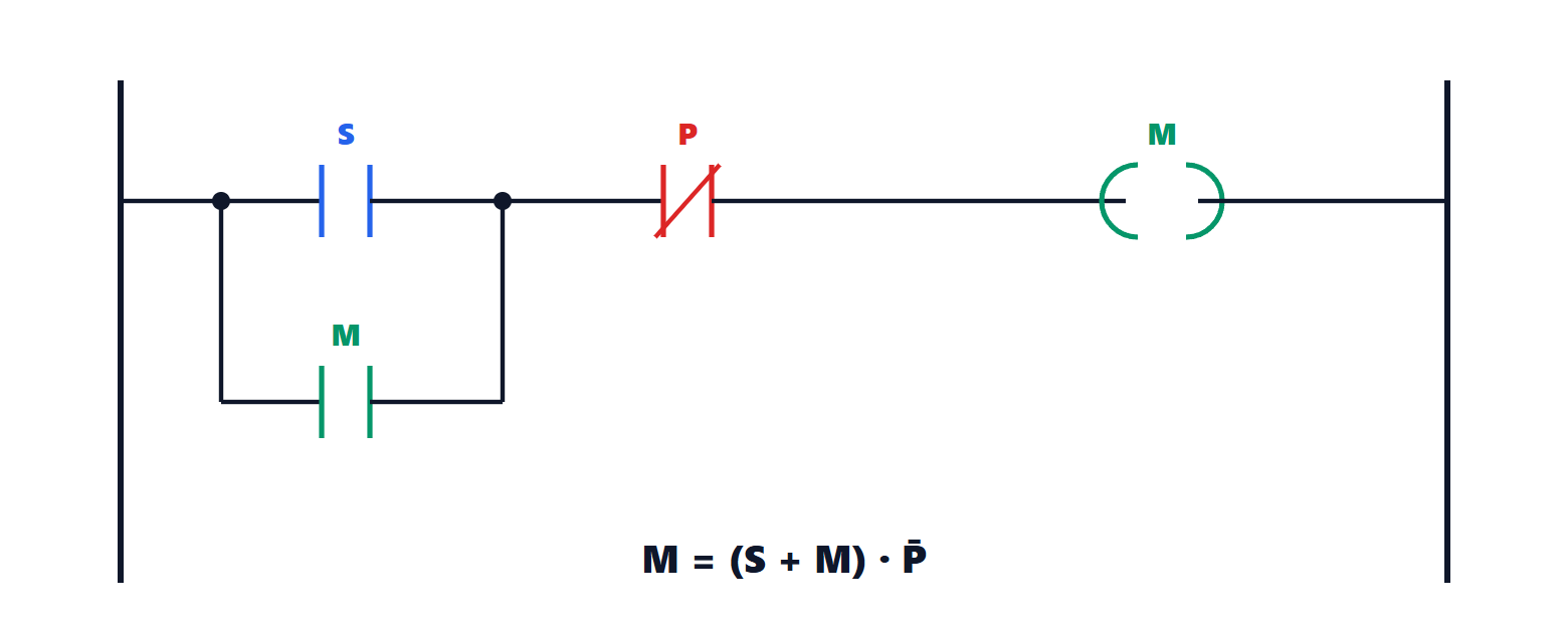
The logic equation is

where  is OR,
 is AND and the bar is NOT. Pressing S energises the coil; at the next cycle the contact of M, in parallel with S, keeps it energised even if S returns to zero: it is a memory, made by feeding the output back to the input, like the latches of the Digital Systems Electronics lesson on latches and flip-flops. Pressing P opens the chain and the motor stops. If S and P are pressed together the stop wins: it is a safety choice.
An important practical detail: the stop button is wired normally closed, so the PLC input is 1 at rest and 0 when pressed. If the wire breaks the input goes to 0 as if stop had been pressed, and the machine stops instead of becoming impossible to stop. In the program a normally open contact is then used on that input, and the logic remains that of the equation. This principle is called fail-safe design.
Timers, counters and sequences
The program uses standard blocks: the on-delay timer (TON) sets its output to 1 if the input stays at 1 for a preset time, for instance to give a star-delta motor starter time to run up; the counter (CTU) counts rising edges, for instance the parts in a pack.
Automatic machines work in sequences: load, close, seal, cut, unload, repeat. In SFC each operation is a step, active until the transition to the next step becomes true (a limit switch, an elapsed time, a count reached). The chart reads like a flow chart and is the direct translation of a finite-state machine. Packaging machines are the typical example.
Safety of people
Functions that protect people, such as the emergency stop or light curtains, are not entrusted to the program of an ordinary PLC: a software error or a CPU fault must not be able to prevent them. Hard-wired safety circuits or certified safety PLCs are used, with redundant CPUs that check each other, designed to the functional safety standards (IEC 61508, ISO 13849) for the required integrity level (SIL or PL).
The automation pyramid
The PLC sits in the middle of a hierarchy:
- at the bottom the field: sensors, actuators, drives, connected to the I/O modules or, more and more often, through fieldbuses (Profibus, Modbus) and industrial Ethernet networks (Profinet, EtherNet/IP, EtherCAT), which also carry diagnostics and configuration;
- in the middle control: PLCs and, in large process plants, DCSs (distributed control systems), which run hundreds of PID loops with the strategies seen in the previous lessons;
- above, supervision: SCADA and operator panels (HMIs), with mimic displays, alarms, data logging and historical trends;
- at the top, production and business management (MES, ERP), which receives the data and sends the production orders.
Integrating these levels, and the cyber security of industrial networks, once isolated and now connected to the internet, are the most current challenges of automation.