Excellent Applied Electronics Exercises
This page publishes the notes for the exercise sessions of the Applied Electronics course. This page attaches worked exercises in applied electronics. In the related topics below…
https://www.electronics-engineering.com/en/excellent-applied-electronics-exercises/
This page publishes the notes for the exercise sessions of the Applied Electronics course.
This page attaches worked exercises in applied electronics. In the related topics below there are links to other past exam papers without solutions and links to excellent notes, again on applied electronics.
EXERCISE: TWO-STAGE AMPLIFIER
This is a two-stage amplifier with the stages AC-coupled through capacitor C2. As a consequence, the operating point of each transistor is determined independently from the circuit of the DC components, shown in figure 2a. Note that the capacitors have been replaced by open circuits, since in DC their reactance is infinite. The figure also shows the positive directions of the currents in the two transistors. Note that, since the gate current of JFET Q2 is zero, the drain current ID equals the source current IS.
CURRENT MIRRORS AS THE “EQUIVALENT OF IDEAL CURRENT SOURCES”
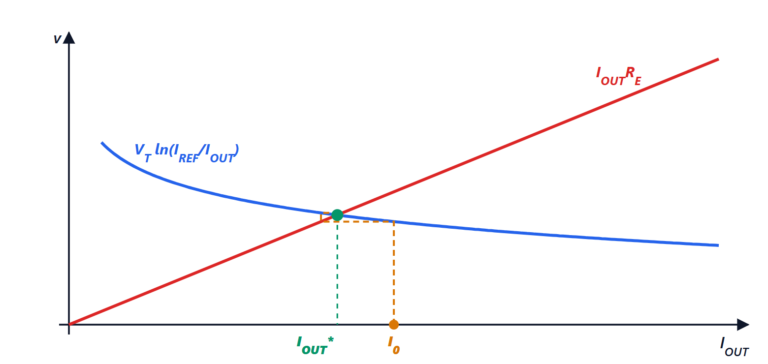
In this lesson we saw current mirrors as the “equivalent of ideal current sources”. We saw the “classic” BJT mirrors and the Wilson mirrors. We saw how feedback makes it possible to increase the output resistance of the latter.
Design a common-emitter amplifier that meets the following specifications:
Load resistance,
Peak amplitude of the output voltage,
Voltage gain,
Input and output resistance
A BJT DIFFERENTIAL AMPLIFIER
In this lesson we saw the design of a BJT differential amplifier. We took the opportunity to make use of the previous lessons by designing its biasing circuitry and understanding the role of the transistors that make up the complete circuit. We calculated the gains of each single stage, the overall gain of the whole amplifier and finally the input bias current. The suggested exercises are problems 7.69 to 7.73.
THE EFFECT OF FEEDBACK ON AMPLIFIERS
In this lesson we saw the effect of feedback on amplifiers. Using the concept of macromodels we were able to analyse the frequency and time behaviour of a differential amplifier with two and with three poles. We saw how “intelligent” placement of the poles makes it possible to improve the time response of a system; finally we saw how, by acting on the loop gain, it is possible to stabilise an amplifier that – wrongly sized – is unstable.




Sono l'autore di questa pagina su «Ottimi Esercizi di Elettronica Applicata». Se qualcosa non è chiaro, se vi serve un esempio in più o volete approfondire un punto, scrivetelo qui sotto nei commenti: rispondo personalmente. Se la pagina vi è stata utile, lasciate un voto con le stelle in cima all'articolo.
gli appelli non svolti di elettronica applicata si trovano al seguente indirizzo:
http://www.ielettronica.it/articolo_4458-appelli_non_svolti_di_elettronica_applicata.htm
nella seguente pagina ottime dispense complete di elettronica applicata:
http://www.ielettronica.it/articolo_4457-ottimi_appunti_di_elettronica_applicata_completi.htm
Attualmente in questa pagina ci sono degli esercizi per ogni argomento allegato. A breve saranno considerate anche le lezioni.