Current mirrors: simple, Wilson, Widlar and cascode
The simple bipolar and MOS mirror, base current error with proof, the Early effect, beta helper, Wilson, Widlar with proof and example, cascode, PTAT and bandgap references.
In analogue integrated circuits almost every transistor is biased by a current source, and almost every current source is a current mirror: a circuit that copies a reference current, possibly multiplied by a fixed ratio, into one or more branches. Mirrors also serve as high-gain active loads. In this lesson we look at the simple bipolar and MOS mirror and its errors, the variants that correct them (beta helper, Wilson, Widlar, cascode) and how to choose between them.
The simple mirror
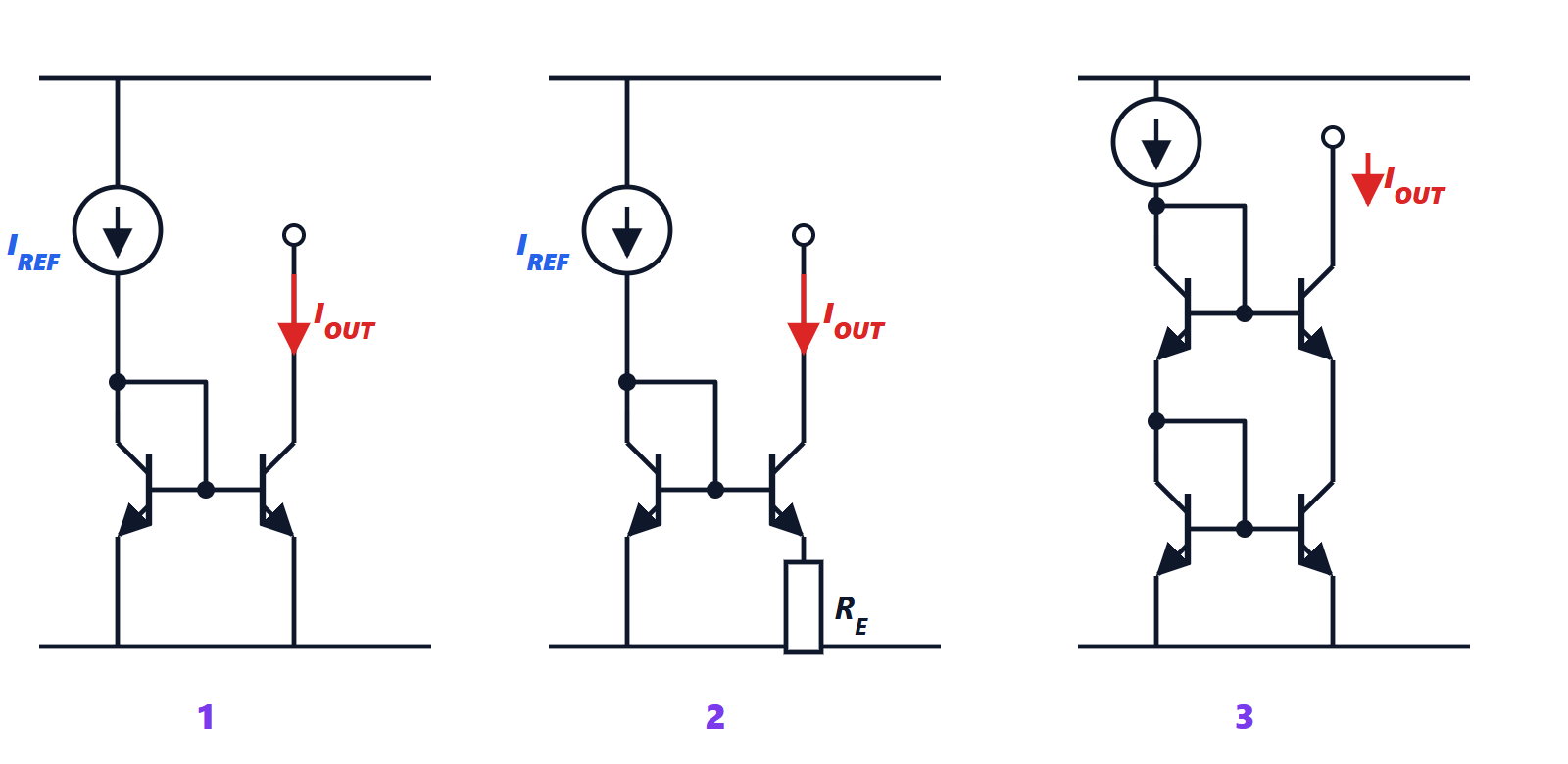
Two identical transistors with their bases tied together and their emitters grounded; the first is diode-connected (base and collector joined). The reference current  sets in the first the
 needed to carry it; the second, with the same , carries the same current:

independently (to first order) of the voltage on its collector, as long as it stays in the active region. With transistors of different area (or several transistors in parallel) the currents are in the ratio of the areas:  .
The MOS mirror works the same way with the square law: same  , so
 . There are no gate currents, so no error of that kind, and the ratio is set precisely by drawing the widths.
Errors of the simple mirror
Base currents. The reference current must also supply the two base currents.
Theorem. In the simple bipolar mirror with identical transistors of gain  ,
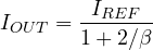
Proof. The two transistors have the same and therefore the same collector current  , and the same base current
 . At the collector node of the first transistor,
 . ∎
With  the output is 98% of the reference, a 2% error that varies with and temperature.
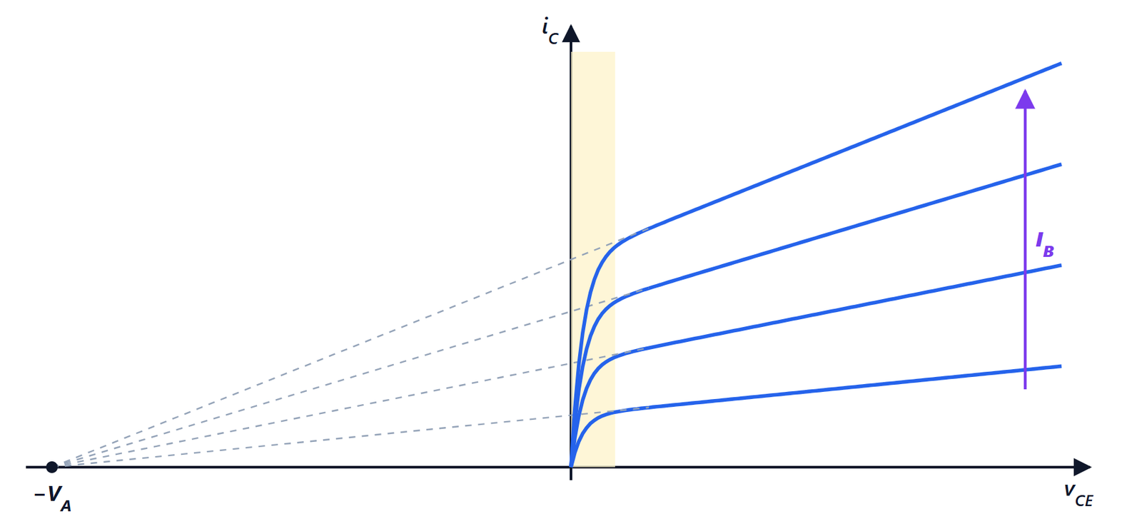
The Early effect. The two transistors have different  : the first
 V, the second whatever the load imposes. Because of the Early effect (Electronic Devices lesson on the BJT) the output current grows with : the mirror has a finite output resistance
 , about 100 kΩ at 1 mA with
 V. In short-channel MOSFETs the error is larger: with
 V⁻¹, 0.7 V on the reference transistor and 3 V on the output one, the output current is 11% higher than expected.
Variants
Beta helper. A third transistor, as an emitter follower, supplies the base currents instead of the reference: the error drops to  , 0.02% with .
Wilson mirror. Three transistors in which current feedback corrects both the base error (which becomes 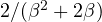 ) and the output resistance, which rises to about
 . For decades it was the precision mirror of bipolar circuits.
Widlar mirror. To get very small currents (microamperes) from a reasonable reference, a resistor  is placed in the emitter of the output transistor.
Theorem. In the Widlar mirror
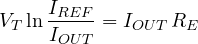
Proof. The bases are tied together, so  (neglecting base currents). With
 for both,
 . ∎
Example. From 1 mA to 10 µA:  kΩ. A simple mirror would need a 100 to 1 area ratio, or a 10 µA reference made with a resistor of about 1 MΩ: both would take a huge area on the chip. The emitter resistor also raises the output resistance.
Cascode mirror. Two stacked mirrors: the upper transistor of the output branch, with its base (or gate) at a fixed voltage, holds the voltage on the lower transistor constant, so it no longer feels load variations. The output resistance is multiplied by the intrinsic gain of the upper transistor: about  for bipolars and
 for MOS. With
 mA/V and
 kΩ it goes from 100 kΩ to about 10 MΩ. The price is the minimum voltage across the mirror, which doubles (about two , or
 in the simple MOS version): with low supplies “wide-swing” versions are used, which cut this loss to
 .
| Mirror | Ratio error (bipolar) | Output resistance | Minimum voltage |
|---|---|---|---|
| simple |  |  |  |
| beta helper | about  | | |
| Wilson | about | about |  |
| Widlar | depends on | greater than |  |
| cascode | | or  | |
Where the reference current comes from
A mirror copies, but does not create: the current must come from somewhere. A simple resistor to the supply gives a current that varies with the supply itself. Integrated circuits therefore use self-biased references, in which two transistors at different current densities produce a difference equal to  , proportional to absolute temperature (PTAT) and independent of the supply. Combining this voltage, which grows with temperature, with a , which falls, gives the bandgap reference of about 1.2 V, stable over temperature, found in almost every analogue and mixed-signal chip.
Where they are used
- Biasing: a single reference and a multi-output mirror feed all the stages of an op-amp, with currents in precise ratios.
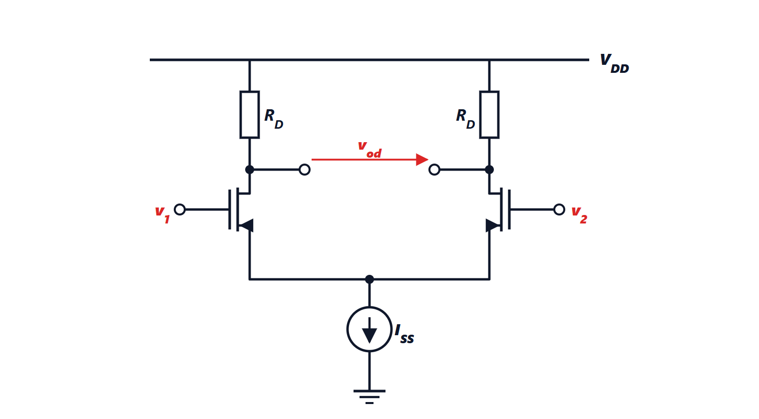
- Tail sources of differential pairs, where high output resistance improves CMRR.
- Active loads, as seen in the lesson on differential amplifiers.
- Current-steering digital-to-analogue converters: dozens or thousands of identical mirrors whose currents are steered to the output according to the digital code. It is the architecture of the fastest DACs, for radio and video signals.
All these circuits rely on transistor matching, which on the chip is cared for with the same techniques seen for the differential pair: large transistors, close together, with the same orientation and arranged in common-centroid fashion.