Output stages: classes A, B, AB and D
Class A and its efficiency, class B push-pull with proven maximum efficiency, transistor dissipation, crossover distortion and class AB, class D amplifiers.
The last stage of an amplifier must deliver power to a load: an 8 Ω loudspeaker, a motor, a line. Here gain alone no longer matters, but efficiency: all the power drawn from the supply and not delivered to the load becomes heat in the transistors. In this lesson we compare classes A, B, AB and D, derive the maximum efficiency of class B and look at crossover distortion.
Class A
The transistor conducts over the whole signal period, biased at the middle of its swing: the quiescent current is at least equal to the peak load current. It is the most linear stage, but it consumes power even with no signal. With a resistive load and resistor biasing the maximum efficiency is 25%, with a transformer or a current source 50%: a 10 W class A amplifier heats up like a 30 to 40 W heater.
Class B
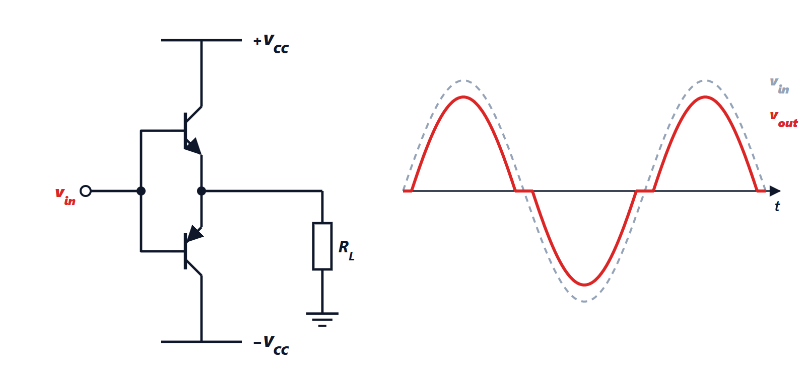
Two complementary transistors, an npn conducting the positive half-waves and a pnp conducting the negative ones (push-pull), each as an emitter follower. At rest neither conducts, and the power drawn is proportional to the signal.
Theorem. With supplies  , load
 and a sinusoidal output of amplitude
 , the efficiency of ideal class B is

and at most  .
Proof. The load power is  . Each supply delivers current only for half the period, a sinusoidal half-wave of peak
 , whose average over the whole period is
 . The two supplies together provide
 . The ratio is
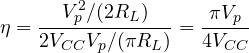
largest for  . ∎
Example. With  V into 8 Ω, the maximum power is
 W, with about 3.9 W dissipated in the transistors. Curiously, maximum dissipation does not occur at full power, but at
 , about 64% of the swing: that is what the heat sink must be sized for.
Crossover distortion and class AB
A bipolar transistor conducts only when  exceeds about 0.6 V. With the bases tied directly to the input, for signals between −0.6 and +0.6 V neither transistor conducts, and the output stays still: this is crossover distortion, particularly annoying because it weighs most on weak signals.
The solution is class AB: the two bases are biased with a difference of about 1.2 V (two diodes in series, or a  multiplier), so both transistors carry a small quiescent current and the handover from one to the other is gradual. Efficiency stays close to class B. Two details matter: the bias diodes are mounted on the same heat sink as the transistors, so that their voltage tracks the thermal drift of (−2 mV/°C) and prevents thermal runaway; and small emitter resistors (fractions of an ohm) further stabilise the quiescent current. Almost all linear audio amplifiers and op-amp output stages are class AB.
Class D
The transistors no longer work in the active region but as switches: the output toggles between the two supplies at hundreds of kilohertz, with a duty cycle proportional to the signal (pulse width modulation, PWM). An LC low-pass filter reconstructs the audio signal. An ideal switch dissipates nothing (either the current through it or the voltage across it is zero), and real efficiencies exceed 90%. It is the technology of the amplifiers in phones, Bluetooth speakers, televisions and professional systems: no huge heat sinks, longer battery life. The price is careful design of the filter and the layout, so as not to radiate interference.
| Class | Conduction | Maximum efficiency | Typical use |
|---|---|---|---|
| A | whole period | 25-50% | preamplifiers, high-end audio |
| B | half period per transistor | 78.5% | rare on its own (crossover distortion) |
| AB | slightly more than half period | about 70% | linear audio, op-amp outputs |
| D | switching | over 90% | portable and power audio, motor drives |