Solved current mirror exercises, from basic to exam level
Twelve exercises with solutions: simple BJT and MOS mirror, current ratios, Early effect, Wilson, cascode, Widlar, helper transistor, multi-output mirrors, active load and supply sensitivity.
Exercises on current mirrors of the kind set in Applied Electronics and Analogue Electronics courses, in three levels: basic, for direct use of the formulas; intermediate, with design and errors; exam, with complete circuits as in written exams. The result is given straight away; the full solution opens with a click. The proofs of the formulas are in the lesson and the in-depth study linked at the top.
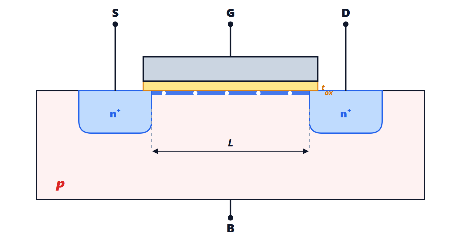
Unless stated:  V,
 mV, identical transistors.
Basic level
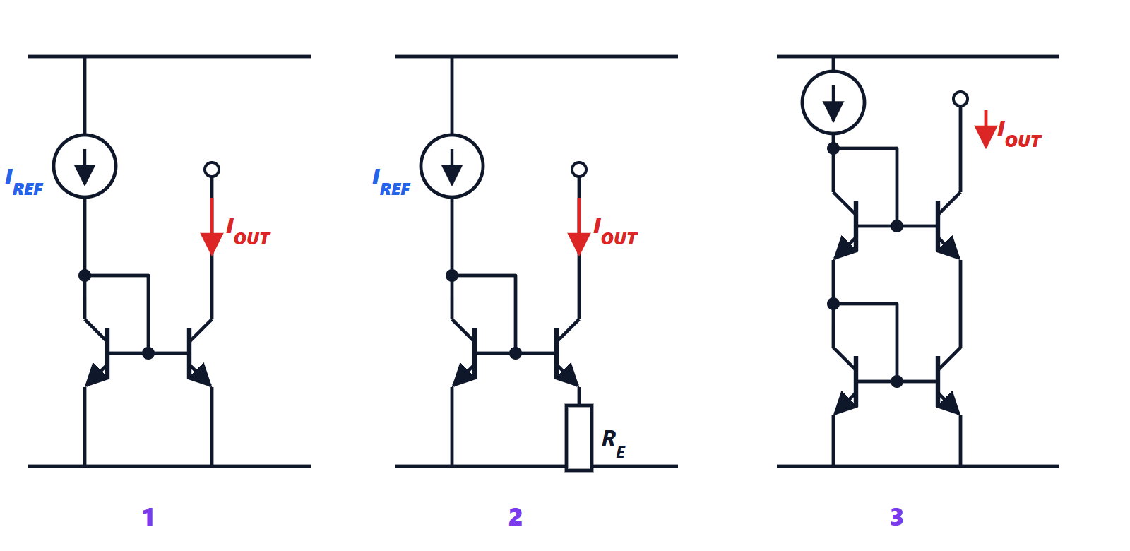
Exercise 1. The simple bipolar mirror
A simple mirror is supplied from  V; the reference current is set by a resistor
 kΩ between the supply and the collector of the diode-connected transistor. With
 , what are
 and
 ?
Result:  mA;
 mA.
Solution
The collector of the diode-connected transistor sits at  : the drop across the resistor is
 V, so
 mA.
Base-current error (lesson):  mA.
Exercise 2. Mirror with an area ratio
An output of about 3 mA is wanted from a 1 mA reference using transistors with emitter areas in the ratio 3 to 1. With , what exactly is ?
Result: 2.885 mA.
Solution
With areas in the ratio  , at the same
 the currents are
 and
 , and the base currents
 and
 .
Reference node:  . So
 mA and
 mA.
In general  : the error grows with the copy ratio, because the large transistor needs more base current.
Exercise 3. The MOS mirror
A MOS mirror has  ,
 and
 µA. Compute neglecting channel-length modulation, and then with
 V
 ,
 V and
 V.
Result: 400 µA; with channel-length modulation 431 µA.
Solution
Without modulation:  µA.
With modulation (in-depth study):  µA, an 8 % error, due solely to the difference in
 between the two transistors.
Exercise 4. Output resistance
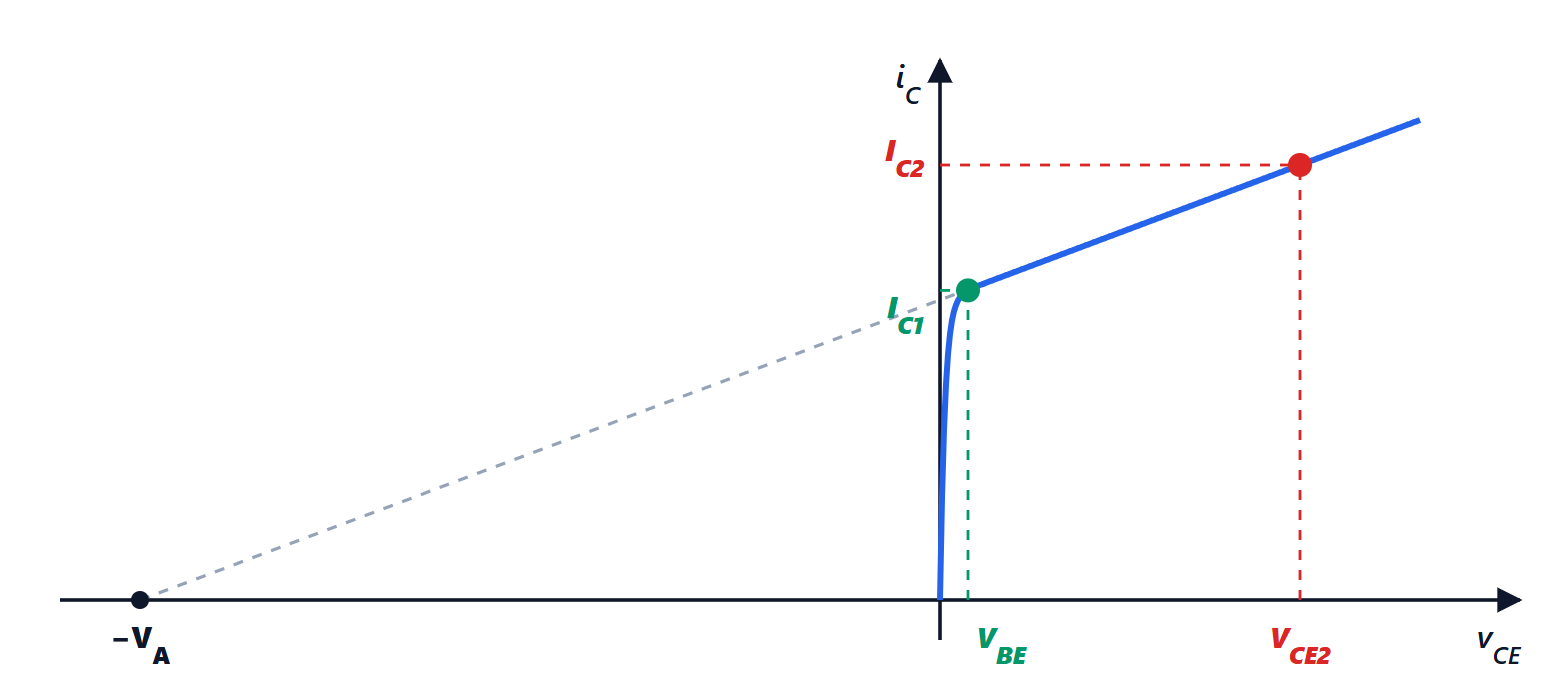
A simple bipolar mirror supplies 0.5 mA, with  V. By how much does the current change if the voltage on the output collector goes from 1 V to 5 V?
Result: about 25 µA, 5 %.
Solution
 kΩ. A 4 V change produces
 µA, i.e. 5 % of 0.5 mA. For an ideal current source it would be zero: the output resistance is the parameter measuring how close the mirror comes to ideal.
Intermediate level
Exercise 5. Design of a Widlar mirror
From a 1 mA reference an output of 20 µA is wanted with a Widlar mirror. What must the emitter resistor be? Compare with the alternative of a simple mirror with a 20 µA reference obtained with a resistor from V.
Result:  kΩ; the alternative would need about 465 kΩ.
Solution
From the lesson’s formula:  kΩ.
Simple mirror with a 20 µA reference:  kΩ. On an integrated circuit a resistor of that value takes up an enormous area compared with a 5 kΩ one: this is the reason for the Widlar mirror.
Exercise 6. Analysis of a Widlar mirror
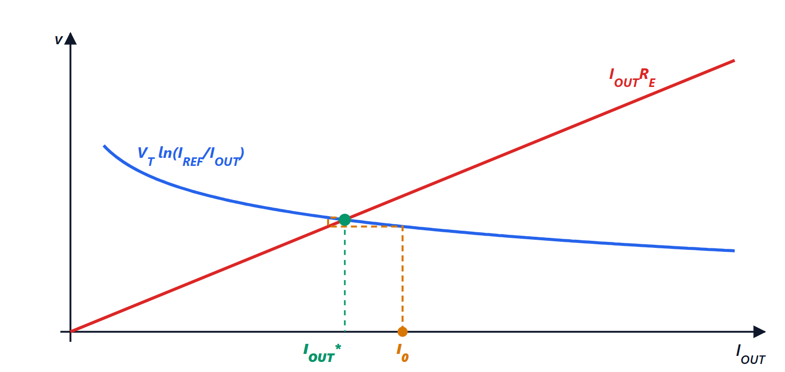
A Widlar mirror has  mA and
 kΩ. Find .
Result: about 41 µA.
Solution
The equation  is transcendental and is solved by iteration (in-depth study), written as
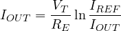 , with
 µA.
Starting from 50 µA:  µA. Then
 µA. Then
 µA. Then
 µA. Then 41.3 µA: the solution is about 41.3 µA.
Check:  V and
 V. The iterates oscillate around the solution, narrowing, as expected from a negative derivative less than 1 in magnitude.
Exercise 7. The helper transistor
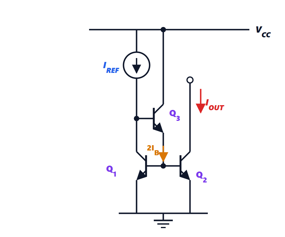
With transistors of  and mA, compare the output current of the simple mirror and of the one with a helper transistor.
Result: simple 0.962 mA (3.8 % error); with helper 0.999 22 mA (0.078 % error).
Solution
Simple mirror:  mA.
With a helper transistor (in-depth study):  mA.
The error is reduced by a factor of about  : with low-
 transistors, such as the lateral PNPs of integrated circuits, the helper transistor is almost indispensable.
Exercise 8. The Wilson mirror
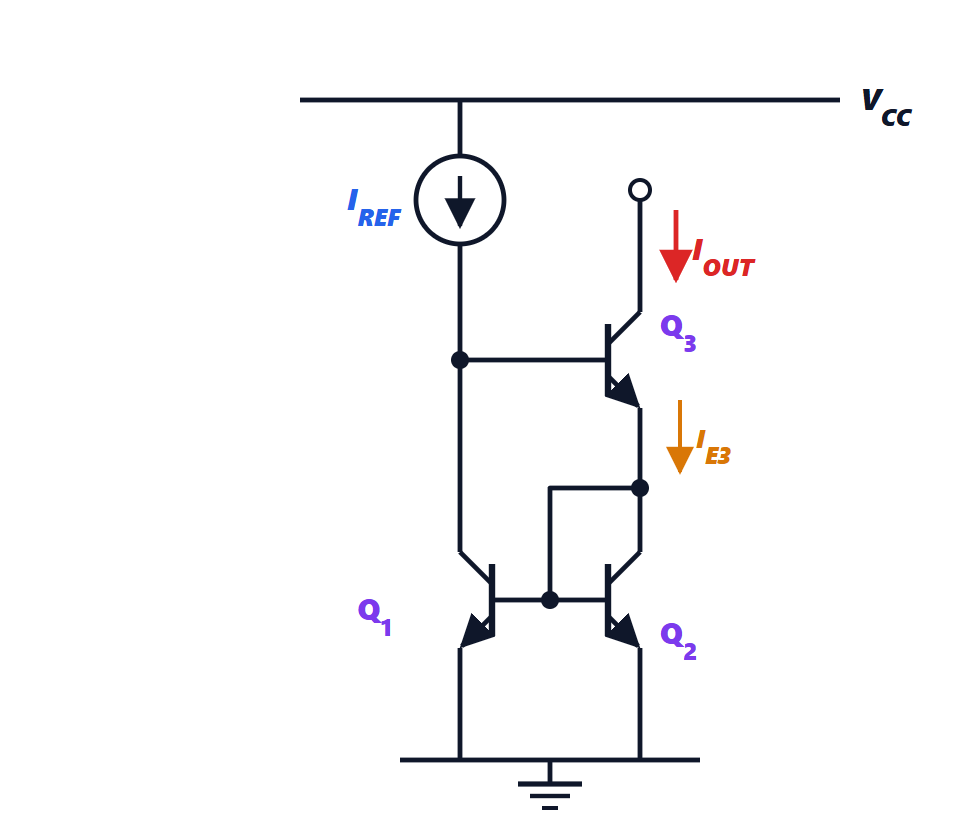
A Wilson mirror with transistors of and  kΩ. Compute the error in the copy ratio and the output resistance, and compare them with those of the simple mirror.
Result: error 0.0196 % (simple 2 %);  MΩ (simple 100 kΩ).
Solution
Error (in-depth study):  , i.e. 0.0196 %, against
 , about 2 %, for the simple mirror.
Output resistance:  MΩ, fifty times that of the simple mirror ( kΩ).
Exercise 9. The MOS cascode
A MOS cascode mirror uses transistors with  mA/V and
 kΩ,
 V and
 V. Compute the output resistance and the minimum output voltage in the simple and wide-swing versions.
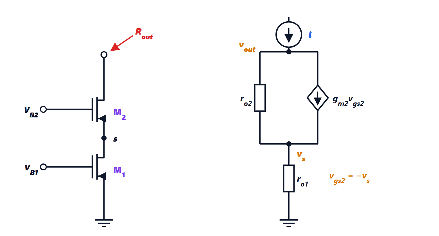
Result:  MΩ; minimum voltage 0.9 V (simple) and 0.4 V (wide-swing).
Solution
Resistance (in-depth study):  MΩ, fifty times that of a single transistor.
Minimum voltage: simple  V; wide-swing
 V.
Exam level
Exercise 10. Biasing a circuit with a multiple-output mirror
A multiple-output bipolar mirror is supplied at 5 V; the reference is set by a resistor. The outputs must have currents in the ratios 1, 2 and 4 relative to the reference transistor, which must conduct 0.5 mA. With :
- size the reference resistor neglecting base currents;
- compute the actual currents taking base currents into account;
- compute the error that would result from adding a helper transistor.
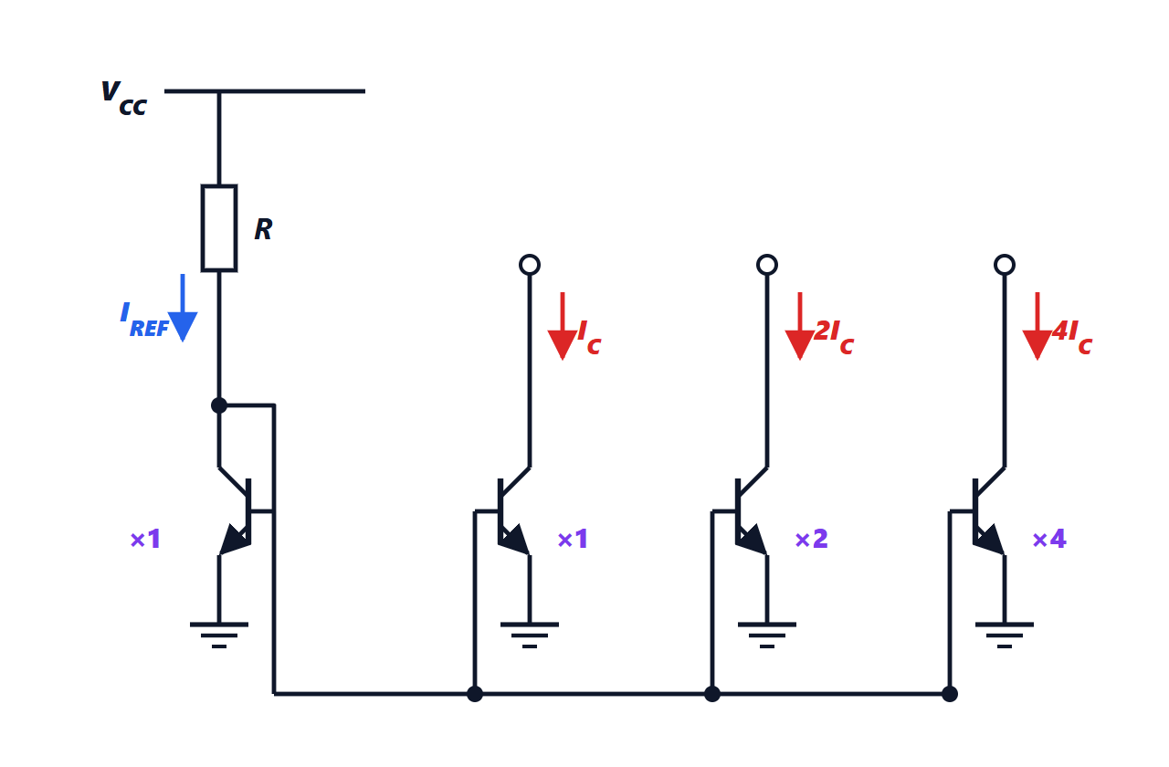
Result:  kΩ; outputs 0.463, 0.926, 1.852 mA (7.4 % error); with the helper transistor an error of about 0.08 %.
Solution
1.  kΩ, giving
 mA.
2. The transistors have areas in the ratio 1 (reference), 1, 2, 4. The collector currents are  , ,
 ,
 , and the base currents total
 . At the reference node
 , so
 mA. Outputs: 0.463, 0.926 and 1.852 mA, all 7.4 % below the intended value.
3. With the helper transistor the base currents  are supplied by its emitter, and only
 is drawn from the reference:
 , error
 , about 0.08 %. Mirrors with many outputs almost always need the helper transistor.
Exercise 11. The stage with an active load
A common-emitter amplifier is biased at  mA and has as its load a PNP mirror supplying the same current. Both transistors have
 V. Compute the open-circuit voltage gain and compare it with that obtained with a 5 kΩ load resistor.
Result: about  (66 dB) with the active load;
 (46 dB) with the resistor.
Solution
 mA/V. The two output resistances are
 kΩ each.
With the active load the collector sees  and
 in parallel: 50 kΩ. Gain
 , i.e. 66 dB.
With a 5 kΩ resistor (in parallel with  , almost negligible):
 , 46 dB. To get the same gain with a resistor 50 kΩ would be needed, with a 50 V drop at 1 mA: impossible with normal supplies. The mirror gives a high resistance for small signals and a small DC drop.
Exercise 12. Supply sensitivity
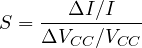
The reference of a mirror is obtained with a resistor from the supply  V. Compute the sensitivity of the current to the supply,
 , and the change in current if the supply rises by 10 %. What solution is used in integrated circuits?
Result:  ; the current rises by about 11.6 %.
Solution
 , so
 and

A 10 % increase (0.5 V) takes the current from  to
 : +11.6 %, more than the supply itself.
Integrated circuits use self-biased references, in which the current is set by a difference across a resistor,  , independent of the supply (lesson, last section); combined with a they give the bandgap reference.