Oscillators: Barkhausen, Wien bridge, Schmitt trigger and crystals
The Barkhausen criterion, the Wien bridge oscillator with proof, the Schmitt trigger and hysteresis, the relaxation oscillator period with proof, the NE555 and crystals.
Every digital circuit needs a clock, every radio a local oscillator, every switching power supply a reference waveform. Oscillators are amplifiers with deliberate positive feedback. In this lesson we cover the Barkhausen criterion, the Wien bridge oscillator, the Schmitt trigger and the relaxation oscillator, and we touch on quartz crystals.
The Barkhausen criterion
An amplifier  with a feedback network
 returning the output to the input in phase (positive feedback) can sustain a sinusoidal oscillation with no input at all if, at frequency
 ,

that is a loop gain of magnitude 1 and phase 0° (or a multiple of 360°). The signal goes round the loop and comes back identical: it sustains itself. It is the same critical point as the Nyquist criterion seen from the other side: there it was to be avoided, here it is sought.
In practice the oscillation starts from noise, so at switch-on the loop gain must be slightly greater than 1: the amplitude grows until some nonlinearity (amplifier saturation, a limiter, automatic gain control) brings the average gain back to exactly 1.
The Wien bridge oscillator
The feedback network is a band-pass made of a series RC and a parallel RC.
Theorem. The Wien network with equal resistors  and capacitors
 has, at frequency
 , zero phase and attenuation
 .
Proof. With 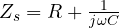 and
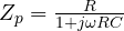 ,
 . Multiplying numerator and denominator by
 :

For  the real term in the denominator vanishes and
 , real. ∎
The amplifier must therefore have a gain of exactly 3: a non-inverting stage with  . With
 kΩ and
 nF one gets about 995 Hz. To stabilise the amplitude, Hewlett and Packard in their first product (1939) used an incandescent lamp in place of
 : as it heats up its resistance rises and reduces the gain just enough. Today diodes or a FET used as a variable resistor do the job.
The Schmitt trigger
A simple comparator changes state when the input crosses a threshold: if the input is noisy and slow, around the threshold the output toggles back and forth dozens of times. The Schmitt trigger solves the problem with positive feedback that creates two different thresholds.
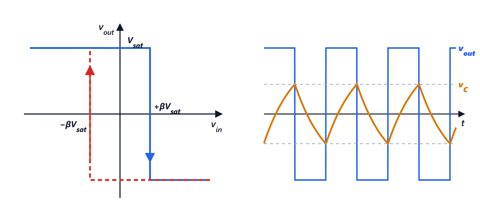
With the output saturated at  and a divider feeding the fraction
 back to the non-inverting input, the thresholds are
 : the signal must cross the whole hysteresis
 to make the output switch again. With
 V,
 kΩ and
 kΩ,
 and the thresholds are ±2.4 V. Schmitt triggers clean up the signals of push-buttons, sensors and long communication lines; many microcontroller inputs have them built in.
The relaxation oscillator
Adding to the (inverting) Schmitt trigger a resistor from the output to the inverting input and a capacitor to ground gives a square-wave generator.
Theorem. The period of oscillation is
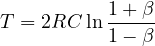
Proof. With the output at  , the capacitor charges towards starting from
 :
 . When it reaches
 the output switches:
 , that is
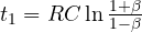 . By symmetry the discharge lasts the same time, and the period is twice that. ∎
Example. kΩ,  nF, :
 ms, about 1.23 kHz. The same principle, with thresholds at 1/3 and 2/3 of the supply, is that of the NE555 timer in its astable configuration.
Quartz crystals
RC oscillators have a frequency that depends on component tolerance and temperature: 1% accuracy at best. For the clocks of microprocessors, watches and radios a quartz crystal is used: a thin plate that, through the piezoelectric effect, vibrates mechanically at a very precise frequency and behaves electrically as a resonant circuit with a quality factor of tens of thousands. A common crystal is accurate to 20 parts per million; the 32 768 Hz ( ) one in watches gives, by halving fifteen times, exactly one pulse per second.