Oscillators: Colpitts, stability and phase noise
Frequency and start-up condition of the Colpitts proved, frequency stability versus Q proved, phase noise and Leeson's model, crystals, TCXO and OCXO.
Every radio has at least one oscillator: it sets the transmit frequency and the conversion frequency in the receiver. It is not enough that it oscillates: it must have the right frequency, stable, and a clean spectrum. In this lesson we look at the oscillation condition, the Colpitts oscillator with the proof of its frequency and start-up condition, the link between quality factor and frequency stability proved, phase noise and its consequences, and crystals.
The oscillation condition
An oscillator is an amplifier with frequency-selective feedback. By the Barkhausen criterion (Applied Electronics lesson on oscillators), a sinusoidal oscillation is sustained at the frequency where the loop gain has magnitude 1 and phase a multiple of 360°. At switch-on the gain must be somewhat greater than 1, so that noise grows into an oscillation; then non-linearity (amplifier compression, lesson on non-linearity) reduces the average gain to 1 and stabilises the amplitude.
The Colpitts oscillator
The Colpitts uses a π network with one inductor and two capacitors, and an inverting amplifier of transconductance  ; the network provides the other 180° of phase shift.
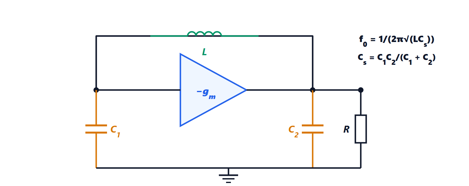
Theorem. The circuit oscillates at the frequency

and starts if  .
Proof. Let  be the input voltage (on
 ) and
 the output voltage (on
 ); the amplifier injects the current
 into the output node. Current law at node 1, where the amplifier input draws no current:
 , hence
 and
 . At node 2:

Substituting and dividing by  :

The imaginary part vanishes if  , i.e.
 , which gives
 . The real part then gives
 : this is the gain that exactly sustains the oscillation, and start-up needs a larger value. ∎
Example.  µH,
 pF:
 pF and
 MHz. With
 kΩ we need
 mS; the design uses a margin of 3-5 times to guarantee start-up over tolerances and temperature. The ratio
 sets how much signal returns to the input.
Quality factor and stability
An oscillator’s frequency shifts when something adds phase to the loop: the transistor capacitance changing with temperature, the supply voltage, the load. A resonator with a high quality factor makes the frequency insensitive to these phase shifts.
Theorem. If a spurious phase shift  appears in the loop, the frequency shifts by about

Proof. Near resonance the impedance phase of a parallel resonator is  , where
 (lesson on resonant circuits). To keep the total loop phase at zero, the resonator must compensate the spurious phase shift, i.e. work at the frequency where
 . ∎
Example. A phase shift of 0.01 rad with an LC resonator of  shifts the frequency by
 , 100 ppm: at 1 GHz that is 100 kHz, unacceptable for a radio channel. With a crystal of
 the shift drops to
 .
Phase noise
Component noise also makes the oscillator’s phase fluctuate: the spectrum is not a line, but a line with two “skirts” on either side. It is measured as phase noise  : the power in a 1 Hz bandwidth at an offset
 from the carrier, relative to the carrier, in dBc/Hz. Leeson’s model estimates it as:

where  is the amplifier’s noise figure and
 the power in the resonator. The resonator converts the amplifier’s phase noise into frequency noise close to the carrier, falling as
 ; again, a high
 and a high power reduce it.
The consequences are practical. In the receiver, a strong signal on an adjacent channel mixes with the local oscillator’s skirts and falls into the wanted channel (reciprocal mixing); in dense digital modulations such as 256-QAM phase noise rotates the constellation points and increases errors (lesson on digital modulation performance).
Crystals
A quartz crystal cut into a plate vibrates mechanically, and through the piezoelectric effect behaves like a resonant circuit with from  to
 , very stable with temperature. It is the reference of almost all oscillators: temperature-compensated crystal oscillators (TCXO) reach a stability of 0.5 ppm, oven-controlled ones (OCXO)
 . High, variable frequencies are obtained by locking a voltage-controlled oscillator to the crystal with a phase-locked loop (Electrical Communications lesson on FM and PLLs), which within its bandwidth inherits its stability and low phase noise.