Non-linearity: intermodulation, compression and mixers
Polynomial model, IIP3 from the two-tone measurement proved, compression point 9.6 dB below IIP3 proved, spurious-free dynamic range proved, diode mixers and the Gilbert cell.
An ideal amplifier is linear; a real one, for large signals, compresses and distorts. In a receiver this means that two strong signals outside the wanted channel can generate a spurious product right inside the channel, masking a weak signal. The mixer, on the other hand, exploits non-linearity on purpose to shift a signal in frequency. In this lesson we look at the polynomial model, third-order intermodulation with the proofs on the intercept point and the compression point, spurious-free dynamic range with an example, and mixers.
The polynomial model
A weak, memoryless non-linearity is approximated by the first terms of a series expansion:

With a single signal  , the quadratic term produces DC and the second harmonic, the cubic term the third harmonic and a term at the fundamental frequency,
 , which adds to
 . If
 has the opposite sign to
 (as in almost all amplifiers, which saturate), the gain drops as amplitude grows: this is compression. Harmonics fall far away and are filtered; the real problem arises with two signals.
Intermodulation
With two close tones,  , the cubic term produces, besides harmonics, components at frequencies
 and
 , of amplitude . These third-order intermodulation products (IM3) fall very close to the original tones, inside the filter band: a receiver tuned to hears a signal that does not exist.
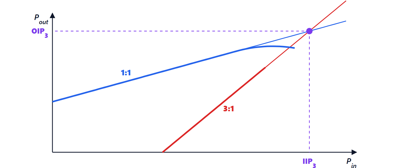
The fundamental term grows as  (1 dB per dB on a logarithmic scale), the intermodulation as
 (3 dB per dB). Extending the two lines, they meet at the third-order intercept point: the input power IIP3 (and the corresponding output OIP3) at which they would have the same level.
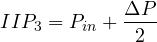
Theorem. If with input power  (per tone, in dBm) the output intermodulation products are
 dB below the fundamentals, then
Proof. In decibels, the output fundamental is  and the intermodulation
 , with
 and
 constants. Their difference is
 . At the intercept point the difference is zero:
 . Subtracting,
 , hence the formula. ∎
Example. With two tones of  dBm each, the intermodulation products come out 60 dB below the fundamentals:
 dBm. The measurement is always made at low levels, in the region where the slopes really are 1 and 3, and extrapolated: the intercept point is never reached, because the amplifier saturates first.
Theorem. For a cubic non-linearity, the 1 dB compression point (the input power at which the gain has dropped by 1 dB) lies about 9.6 dB below IIP3.
Proof. From the first part, the gain with a tone of amplitude is  . It drops by 1 dB, i.e. to the factor 0.891, when
 , so
 . At the intercept
 , so
 . The power ratio is
 , i.e.
 dB. ∎
For a chain of stages, the final stages are the most critical: the signal reaches them already amplified. In linear units  , dual to Friis’s formula for noise: noise is decided by the first stage, linearity by the last.
Spurious-free dynamic range
A receiver has a lower limit, the noise floor  in its bandwidth, and an upper limit, the level at which intermodulation emerges from the noise. The spurious-free dynamic range (SFDR) is the distance between the two.
Theorem.  , with all quantities in dB referred to the input.
Proof. Referred to the input, intermodulation is  (a line of slope 3 equal to
 when
 ). Setting it equal to the noise:
 . The dynamic range is
 . ∎
Example. Noise floor  dBm, IIP3
 dBm: SFDR
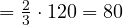 dB.
Mixers
A mixer shifts a signal in frequency by multiplying it by a local oscillator: by the identity  , a signal at
 multiplied by
 produces components at
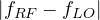 and
 (lesson on the superheterodyne receiver). Any non-linear device can act as a mixer through its quadratic term, but real mixers are designed to approach a multiplier:
- the balanced diode ring mixer, passive, very linear, with a conversion loss of about 6 dB;
- the Gilbert cell, with two cross-coupled differential pairs switched by the local oscillator: an integrated multiplier with conversion gain, used in almost all integrated transceivers;
- passive CMOS switching mixers, transistors used as switches, very linear and with low flicker noise.
The balanced structure cancels the local oscillator and the input signal at the output, which would otherwise saturate the following stages or radiate from the antenna. In mixers the same parameters as amplifiers count (gain, noise, IIP3), plus the isolation between ports.