Negative feedback in amplifiers
The fundamental equation with proof, desensitisation, bandwidth extension, distortion, effect on impedances in the four topologies, stability and dominant-pole compensation.
Negative feedback is the most important idea in analogue electronics. Invented by Harold Black in 1927 for telephone line amplifiers, it makes it possible to build precise, linear circuits from imprecise, nonlinear components, in exchange for part of the gain. In this lesson we derive the fundamental equation and its effects on gain, bandwidth, impedances and distortion, and we look at the price to pay: the risk of instability.
The fundamental equation
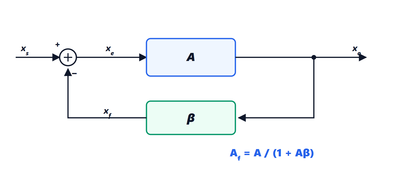
Theorem. The gain of the feedback amplifier is
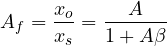
Proof. From the diagram  ,
 ,
 . Substituting,
 , that is
 . ∎
The product  is the loop gain. If
 ,
 : the gain depends only on the feedback network, made of precise, stable passive components.
Effects of feedback
Desensitisation. Differentiating, 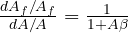 : a 20% change in transistor gain (from temperature, or from one device to another) becomes, with
 , a 0.02% change in the overall gain. It is the same result seen for sensitivity in Automatic Control.
Bandwidth. If  has one pole,
 , the feedback gain is

The in-band gain is reduced by  , but the bandwidth widens by the same factor: the gain-bandwidth product stays constant (lesson on the real op-amp).
Distortion and noise. A real amplifier is not linear: its output contains harmonics that were not at the input. Feedback returns them to the input with the opposite sign and reduces them by  . The same holds for disturbances arising inside the loop (supply hum, load variations), but not for noise entering together with the signal, which is amplified exactly like the signal.
Impedances. It depends on how the feedback samples the output and compares at the input:
| Sampling at output | Comparison at input | Output impedance | Input impedance | Example |
|---|---|---|---|---|
| voltage (shunt) | voltage (series) | divided by | multiplied by | non-inverting |
| voltage (shunt) | current (shunt) | divided by | divided by | inverting, transimpedance |
| current (series) | voltage (series) | multiplied by | multiplied by | current source |
| current (series) | current (shunt) | multiplied by | divided by | current amplifier |
The rule: sampling a voltage, feedback stabilises it, that is it lowers the output impedance (approaching an ideal voltage source); sampling a current it raises the output impedance (approaching an ideal current source). For example the non-inverting amplifier has gigaohms of input impedance and milliohms of output impedance, even though the op-amp alone has far less extreme values.
The price: stability
All the benefits require the feedback to be negative. But has poles, and at high frequencies it introduces phase shift: if at some frequency the loop phase shift reaches 180° while  , feedback turns positive and the circuit oscillates. It is the Nyquist criterion of the Automatic Control lesson, applied to an amplifier. The robustness measures are the same: the phase margin, usually at least 45 to 60°.
The worst case is the follower, with  : the loop gain is the highest possible, and the frequency where
 is the highest. That is why op-amps are internally compensated with a dominant pole at a very low frequency (a few hertz): the gain falls by 20 dB per decade and reaches 1 before the other internal poles add phase shift, so the op-amp is stable in any configuration with
 . The price is the limited gain-bandwidth product. There are “decompensated” op-amps, faster, stable only for gains above a minimum value given in the datasheet.
A practical trap. A capacitive load at the output (a long cable, a converter input) adds a pole in the loop and reduces the phase margin: a follower directly driving a capacitor may oscillate. The remedy is a small resistor (10 to 100 Ω) in series with the output, outside the loop.