Op-amp circuits: integrator, instrumentation amplifier, transimpedance, active filters
The integrator with proof and the differentiator, the three-op-amp instrumentation amplifier with gain proof, transimpedance for photodiodes, Sallen-Key filters.
With an op-amp and a few passive components almost every function of analogue electronics can be built. In this lesson we cover the integrator and differentiator, the instrumentation amplifier for sensors, the transimpedance amplifier for photodiodes, and active filters.
The integrator
Replacing the feedback resistor of the inverting amplifier with a capacitor  : the current
 reaching the virtual-ground node charges the capacitor, and

Proof. The capacitor current is  with
 ; it must equal :
 . Integrating gives the formula. ∎
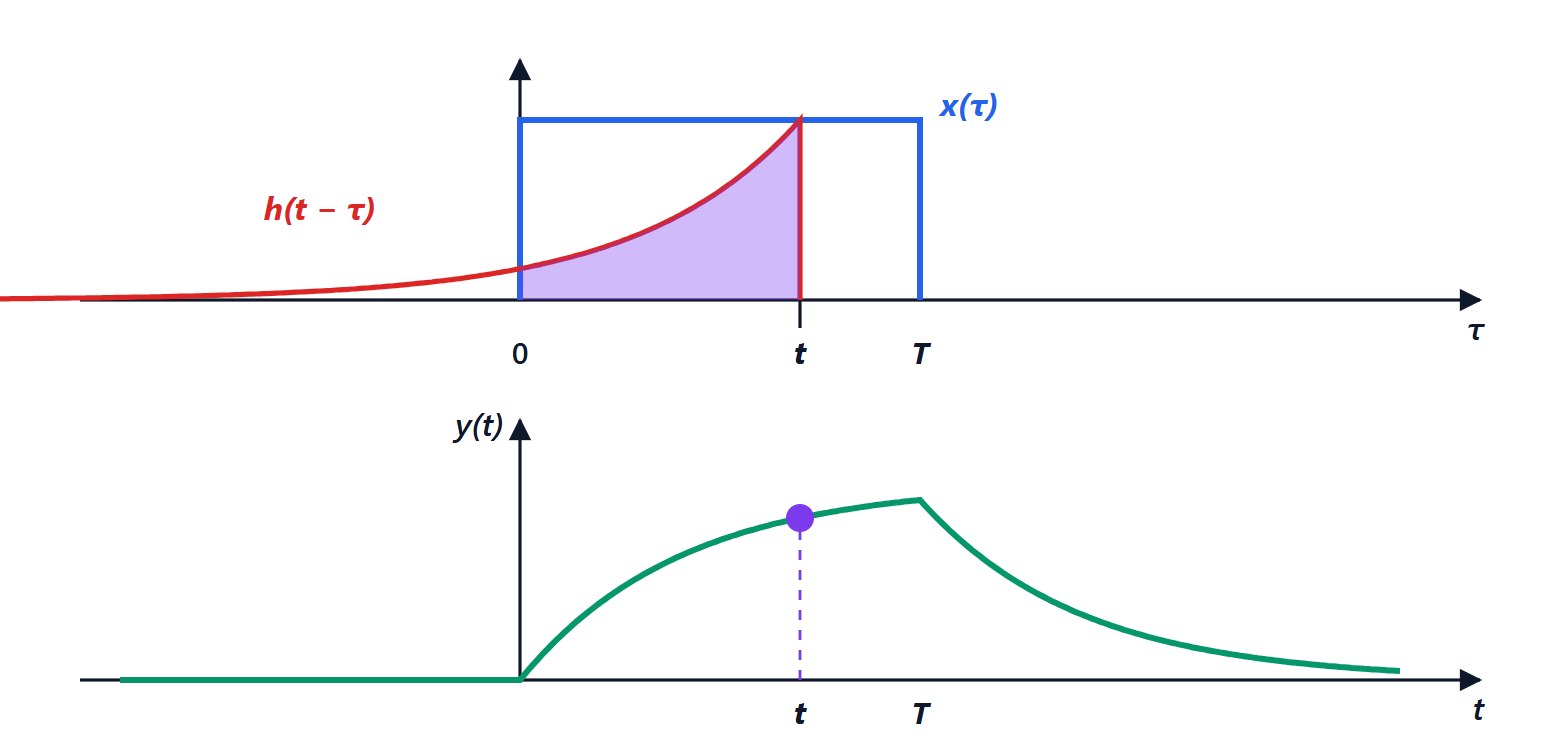
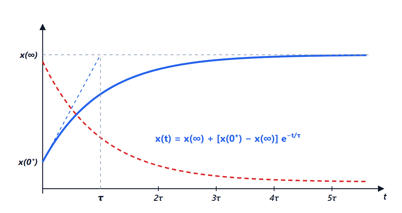
In frequency the gain is  : it falls by 20 dB per decade. The practical problem is that at DC the gain is infinite: even a small offset is integrated until the output saturates. So a large resistor is placed in parallel with the capacitor, limiting the DC gain (lossy integrator), or the capacitor is periodically reset with a switch. Integrators are used in waveform generators, dual-slope analogue-to-digital converters and analogue PI controllers.
The differentiator (capacitor at the input, resistor in feedback),  , has the opposite flaw: its gain grows with frequency and amplifies noise. It is rarely used, and always with a resistor in series with the capacitor limiting its high-frequency gain.
The instrumentation amplifier
A bridge sensor (strain gauge, load cell, resistance thermometer) produces a few millivolts of difference on top of a common voltage of a few volts. It needs an amplifier with very high input impedance on both inputs, a precise differential gain adjustable with a single resistor, and very high common-mode rejection.
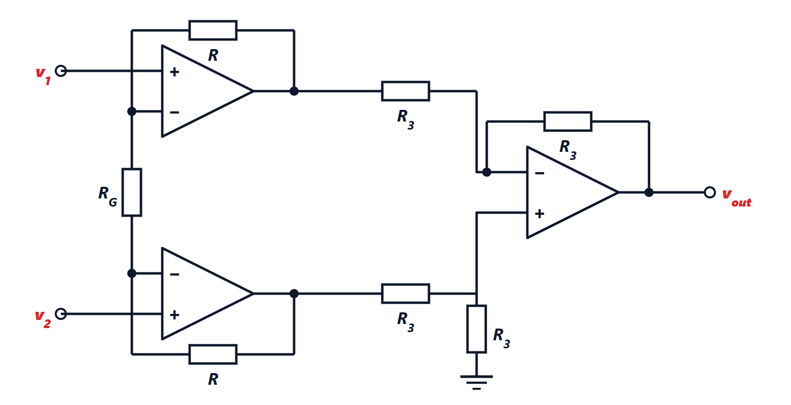
Theorem. The gain of the three-op-amp instrumentation amplifier is
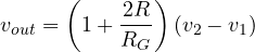
Proof. By the virtual short of the input op-amps, the voltage across  is exactly
 , so the current
 flows in . The same current flows through the two resistors
 , since it cannot enter the op-amps. The outputs of the first two op-amps therefore differ by
 . The third op-amp, a unity-gain difference amplifier, brings this difference to the output (with a sign depending on which input is called
 ). The voltage common to both inputs, instead, passes unchanged through the first stage and is removed by the second. ∎
Example. With  kΩ and
 kΩ the gain is
 . In integrated form (the INA and AD620 parts of datasheets) the internal resistors are laser-trimmed and common-mode rejection exceeds 100 dB: an input of 1 V common to both wires appears at the output as less than 10 µV equivalent.
The transimpedance amplifier
A photodiode produces a current proportional to the light, of nanoamperes or microamperes. Connecting it to the inverting input of an op-amp with a feedback resistor  , the whole current flows in and

The photodiode works at zero voltage (virtual ground), which makes it linear and fast. With  MΩ, 1 µA of photocurrent gives 1 V. A small capacitor in parallel with is almost always needed for stability, because the photodiode capacitance at the input tends to make the circuit oscillate. It is the input stage of optical fibre receivers, remote controls, lidars and pulse oximeters.
Active filters
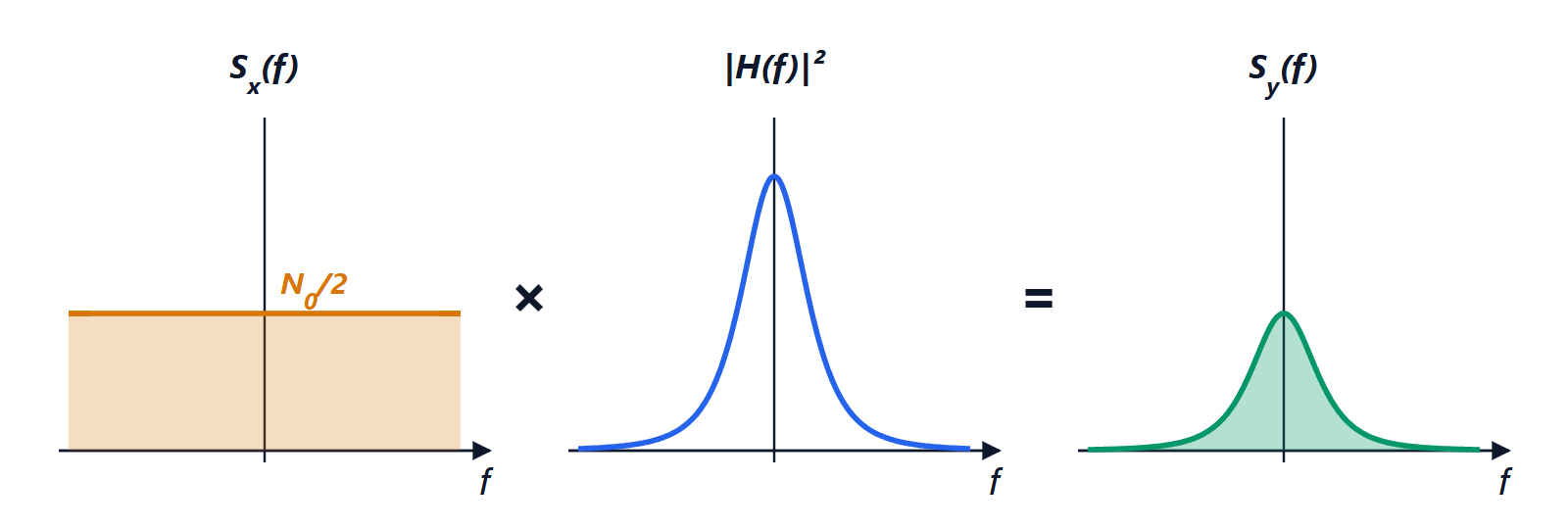
With resistors, capacitors and an op-amp, filters can be built without inductors, which are bulky and expensive at low frequencies. The most used cell is the Sallen-Key: two resistors and two capacitors around an op-amp in non-inverting configuration form a second-order filter (40 dB per decade). With equal resistors , equal capacitors and unity gain, the cut-off frequency is  and the quality factor is 0.5; to get the flattest response (Butterworth,
 ) the capacitor ratio or the stage gain is changed. Cascading several cells gives high-order filters: for example the anti-aliasing filter in front of a converter (Signal Theory lesson on sampling).