Transients in first-order RC and RL circuits
The first-order equation, the general solution with time constant, initial and final values, an example, overvoltage when an inductor is switched off, and second-order circuits.
When a switch closes in a circuit with capacitors or inductors, or a signal changes suddenly, quantities do not jump instantly to their new values: there is a transient, governed by the stored energy. In this lesson we cover the general method for first-order circuits (a single energy-storing element), which gives the solution almost without calculation, and touch on second-order circuits.
The first-order circuit
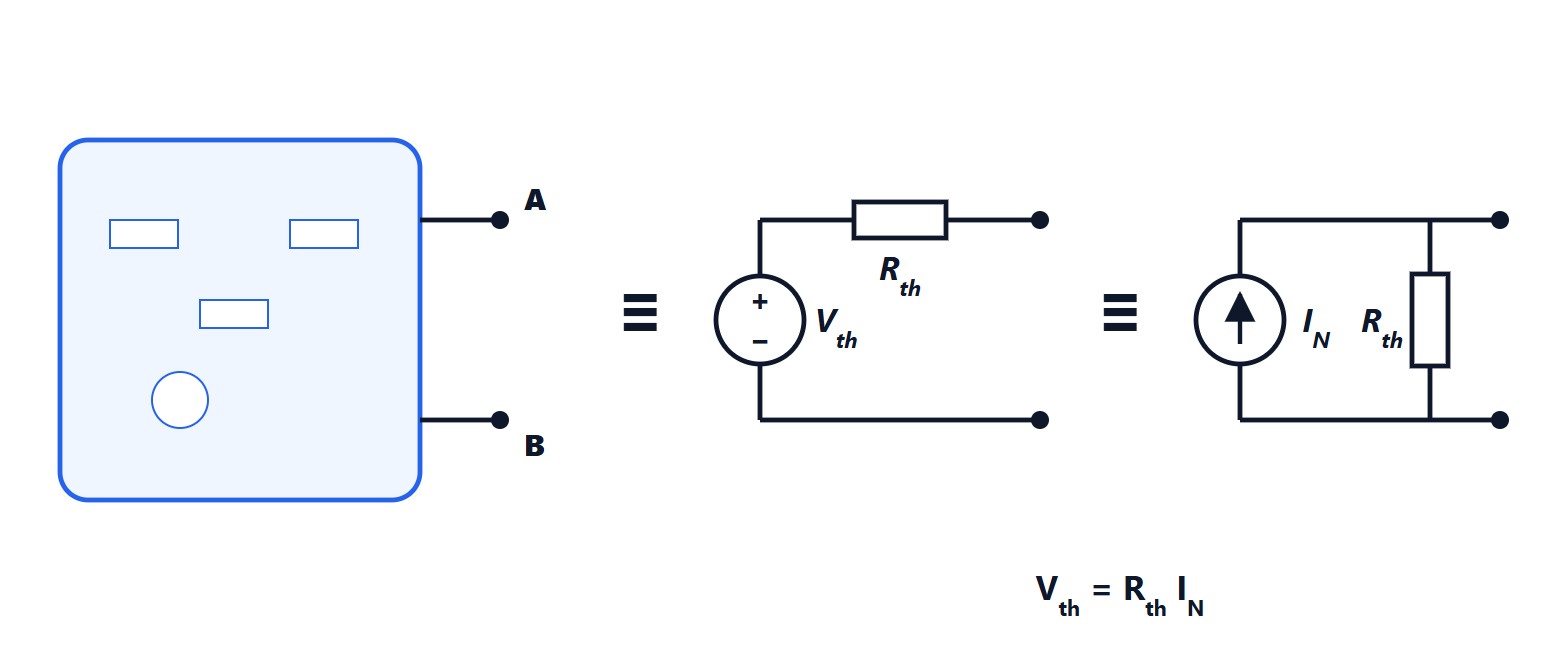
A first-order circuit contains a single capacitor or a single inductor, plus resistors and constant sources. Applying Thevenin’s theorem to the rest of the circuit, seen from the terminals of the storage element, it always reduces to a source  with a resistance
 connected to the capacitor (or inductor).
For the capacitor:  , a first-order linear differential equation (Analysis 2). For the inductor, with the Norton equivalent, the same form is obtained for the current.
The general solution
Any quantity  of a first-order circuit with constant sources, after switching at
 , is

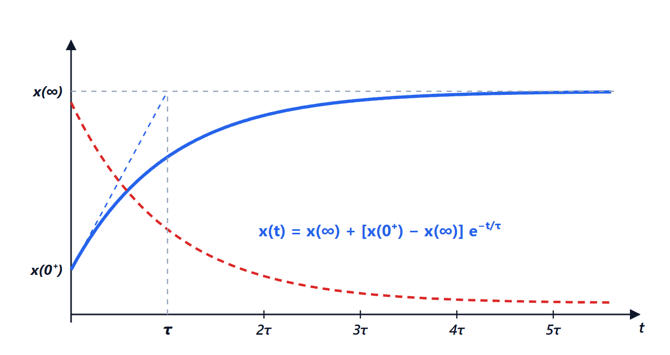
Only three numbers are needed:
- the initial value
 , just after switching;
- the final value
 , at steady state;
- the time constant
 .
How to find the three numbers
The initial value. Use continuity: the voltage on a capacitor and the current in an inductor cannot jump, so  and
 . Other quantities (resistor currents, the inductor voltage) can jump: they are computed at
 replacing the capacitor with a voltage source
 and the inductor with a current source
 .
The final value. At steady state, with constant sources, nothing changes: the capacitor is an open circuit, the inductor a short circuit. Solve the resistive circuit that remains.
The time constant. Switch off the independent sources and compute the resistance seen from the terminals of the storage element:

Example
A 10 µF capacitor, initially empty, is connected through a switch to a divider: a 12 V source,  kΩ in series,
 kΩ in parallel with the capacitor. At the switch closes. What is the capacitor voltage?
- Initial:
 .
- Final: at steady state the capacitor is open and the voltage is the divider’s,
 V.
- Time constant: with the source off, the capacitor sees
 kΩ, so
 ms.

After 12 ms the capacitor is at 4.55 V (63% of the final value), after 60 ms at 7.15 V. No differential equation to solve.
A switch opening on an inductor
A relay has a coil with  H and 50 Ω resistance, fed at 12 V: at steady state 240 mA flows. If a transistor interrupts the current suddenly, the inductor current cannot jump: to keep flowing it must find a path, and the voltage rises until it does, destroying the transistor. With a flyback diode across the coil the current keeps circulating through the diode and dies away with time constant
 ms. It is the most important application of current continuity in inductors.
Inputs that are not steps
With a square wave input the method is applied at each edge, starting each time from the value reached. If the period is much longer than an RC circuit’s output follows the input with rounded edges; if much shorter, the capacitor has no time to charge and the output becomes a nearly flat triangle wave around the average value: the RC circuit integrates. Swapping R and C, the output taken across the resistor shows only the edges: the circuit differentiates. These are the two limiting behaviours of the low-pass and high-pass filters of the lesson on frequency response.
Second order
With a capacitor and an inductor together (an RLC circuit) the equation becomes second order. The behaviour depends on the damping ratio  (for the series RLC): overdamped, critical or oscillating. Solutions and graphs are in the Analysis 2 lesson on differential equations and in the Mathematical Methods lesson on Laplace transform applications, the most convenient tool when circuits get more complex.