Frequency response, RC filters, Bode plots and resonance
The frequency response function, RC low-pass and high-pass filters, decibels and Bode plots, higher-order filters, resonance and band-pass.
A circuit with capacitors and inductors responds differently to different frequencies: it lets some components of a signal through and attenuates others. This is the principle of filters, found in every electronic device: they separate signal from noise, remove 50 Hz hum, select a radio station, protect a converter from aliasing. In this lesson we cover the frequency response, Bode plots, first-order filters and resonance.
Frequency response
With the phasor method, the ratio of a circuit’s output phasor to its input phasor is a function of angular frequency:
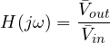
It is the Laplace transfer function evaluated at  (Mathematical Methods lesson). The magnitude
 says how much each frequency is amplified or attenuated, the argument by how much it is phase-shifted.
The RC low-pass filter
With the output taken across the capacitor, by the impedance divider:


- at low frequency (
 ) the capacitor is almost an open circuit:
 , the signal passes;
- at high frequency the capacitor is almost a short circuit:
 , the signal is attenuated;
- at the cut-off frequency
 ,
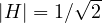 and the phase shift is −45°.
Example. With  kΩ and
 nF,
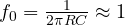 kHz.
Bode plots
The magnitude is plotted in decibels,  , together with the phase, both against frequency on a logarithmic scale. Logarithmic scales turn products into sums, and the plots of complex circuits are built by adding those of their parts.
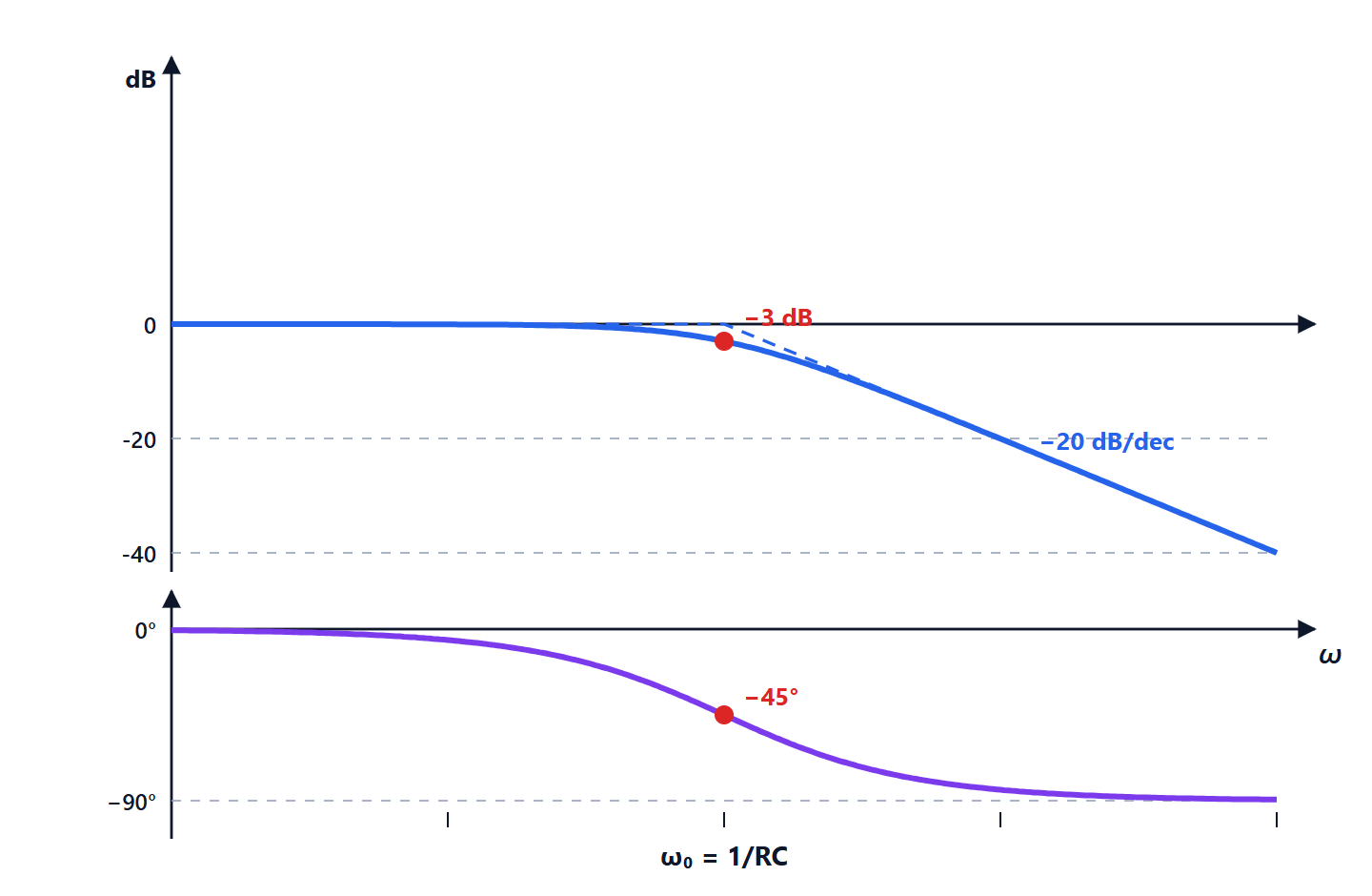
For the first-order low-pass:
- below the magnitude is about 0 dB;
- above it falls by 20 dB per decade (at ten times the frequency the signal is ten times smaller);
- at the error with respect to the asymptotes is largest, −3 dB (half the power).
Decibels are also handy because chains of stages add up: a +40 dB amplifier followed by a filter attenuating 20 dB gives +20 dB overall.
The high-pass
Swapping R and C (output across the resistor):
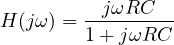
It blocks DC and low frequencies and passes high ones, with a slope of +20 dB/decade below cut-off. It is the coupling capacitor between two amplifier stages: it passes the audio signal and blocks the DC bias voltage. It must be sized so the cut-off lies below the lowest frequency to be passed (20 Hz for audio).
Higher-order filters
A first-order filter separates two nearby frequencies poorly: 20 dB per decade is not much. Cascading stages, or using inductors and capacitors together, gives filters of order  with a slope of
 dB/decade. The classic families shape the response with different trade-offs:
- Butterworth: the flattest possible passband response;
- Chebyshev: a steeper transition, with ripple in the passband;
- Bessel: nearly linear phase, so the waveform is preserved (suited to pulses).
With operational amplifiers, active filters without inductors are built, and that is how almost all filters below a few megahertz are made.
Resonance
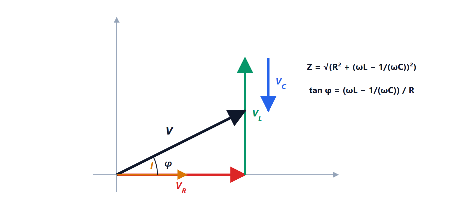
In the series RLC circuit the impedance is  : at the resonant frequency
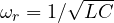 the reactances cancel, the impedance is smallest and the current largest (Physics 2 lesson on AC). Taking the output across the resistor gives a band-pass, centred on
 , with bandwidth
 and quality factor
 . The parallel LC circuit does the opposite: at resonance its impedance is largest, and it is the tuning circuit of oscillators and radio receivers.
Filters and signals
By superposition, a filter treats each Fourier component of a signal separately. A 1 kHz square wave through a low-pass with a 1 kHz cut-off loses most of its high harmonics (3, 5, 7 kHz…) and becomes almost a sine wave: the RC circuit that “rounds” the edges in the lesson on transients is the same phenomenon seen in frequency.