Two-port networks, mutual inductance and the ideal transformer
Z, Y, hybrid and transmission parameters, reciprocity, coupled inductors with proof that k ≤ 1, the ideal transformer and impedance transformation.
Many components and subcircuits have an input port and an output port: an amplifier, a filter, a transmission line, a transformer. To connect them you do not need to know what is inside: the relations between voltages and currents at the two ports are enough. This is the two-port model, which in this lesson we also apply to coupled inductors and to the ideal transformer.
The two-port
A two-port has two pairs of terminals, the ports. At each port the current entering one terminal leaves through the other. There are four quantities:  at the input port and
 at the output port, with both currents taken as entering.
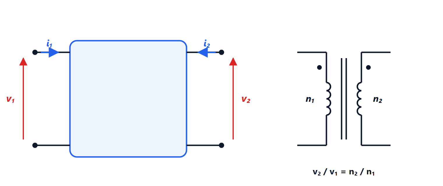
If the internal circuit is linear and contains no sources, two of the four quantities are linear functions of the other two. The possible choices give the different representations.
Parameter matrices
Impedance parameters (currents as inputs):
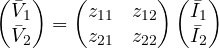
Each parameter is measured with one port open:  with
 ,
 with , and so on.
Example. A T network with  in the input branch,
 in the output branch and
 to ground: with the output open,
 and
 ; by symmetry
 and
 .
The other representations:
- admittance
 (voltages as inputs, short-circuit measurements);
- hybrid
 :
 and
 as functions of
 and
 . These are the ones in bipolar transistor datasheets:
 is the current gain;
- transmission (ABCD): input as a function of output. Their advantage is that for two two-ports in cascade the overall matrix is the product of the two matrices.
Reciprocity. In a circuit made only of resistors, capacitors and inductors (coupled ones included)  holds: the effect of a current at port 1 on the voltage at port 2 equals the reverse one. In the T example you can see it directly. Circuits with controlled sources, like transistor models, are generally not reciprocal.
Coupled inductors
Two nearby coils share flux: the current in one induces a voltage in the other. The equations are

where  is the mutual inductance. Its sign depends on the winding direction, and schematics mark it with a dot: if both currents enter the dotted terminal, the fluxes add and appears with a plus sign. In sinusoidal steady state it is a two-port with
 ,
 ,
 .
Theorem. 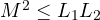 , that is the coupling coefficient
 is at most 1.
Proof. The energy stored in the magnetic field is

and it must be non-negative for any pair of currents, because a passive component cannot give back more energy than it received. With  and
 ,
 is a quadratic in
 with positive leading coefficient: it is non-negative for every only if the discriminant is not positive,
 . ∎
 means all the flux of one coil passes through the other; power transformers with iron cores reach 0.99, while for two distant air coils
 is close to zero.
The ideal transformer
It is the limit of two coils with perfect coupling (), no losses and very large inductances. Wound on the same core, with  and
 turns, they are linked by the same flux
 , and by Faraday’s law
 ,
 . Hence
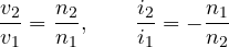
The second relation follows because the ideal transformer neither absorbs nor stores energy:  . The minus sign says that, with entering currents, when current enters the primary it leaves the secondary.
Impedance transformation. With a load  on the secondary, the impedance seen from the primary is
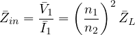
because the voltage is divided by  and the current multiplied by the same factor. It is the classic way to match a load to a source: an 8 Ω loudspeaker, through a transformer with a 10:1 turns ratio, looks like 800 Ω to the amplifier.
Real transformers. A real transformer is modelled by adding to the ideal one a resistance for the windings, an inductance for the leakage flux and a branch for the magnetising current and the iron losses. It works only with AC: with a DC voltage the flux does not change and nothing is induced in the secondary. That is why the power grid is AC: transformers step the voltage up for transmission (at 380 kV the currents, and so the  losses, are small) and back down for use.