Electromagnetic induction: Faraday-Lenz law, transformer and RL circuit
Magnetic flux, the Faraday-Lenz law, motional emf with proof, the alternator, the transformer, eddy currents, self-inductance and the RL circuit.
In 1831 Faraday discovered that a changing magnetic field produces a current in a nearby circuit. It is the discovery on which almost all the world’s electricity generation rests, and on which transformers, switching power supplies, wireless charging, electric guitars and induction hobs work. In this lesson we cover the Faraday-Lenz law, motional electromotive force, self-inductance and the RL circuit.
Magnetic flux
The flux of the magnetic field through a surface is

For a flat loop of area  in a uniform field making an angle
 with the normal,
 . The flux can change in three ways:
 changes, the area changes, the orientation changes.
Faraday’s law and Lenz’s law
The electromotive force induced in a circuit equals minus the rate of change of the linked magnetic flux:

For a coil of  turns,
 .
The minus sign is Lenz’s law: the induced current flows in the direction that opposes the change in flux that caused it. If the flux increases, the induced current creates a field that fights it; if it decreases, a field that props it up. It is not a detail: it is energy conservation. If the induced current helped the change, the effect would feed itself, creating energy out of nothing.
Motional electromotive force
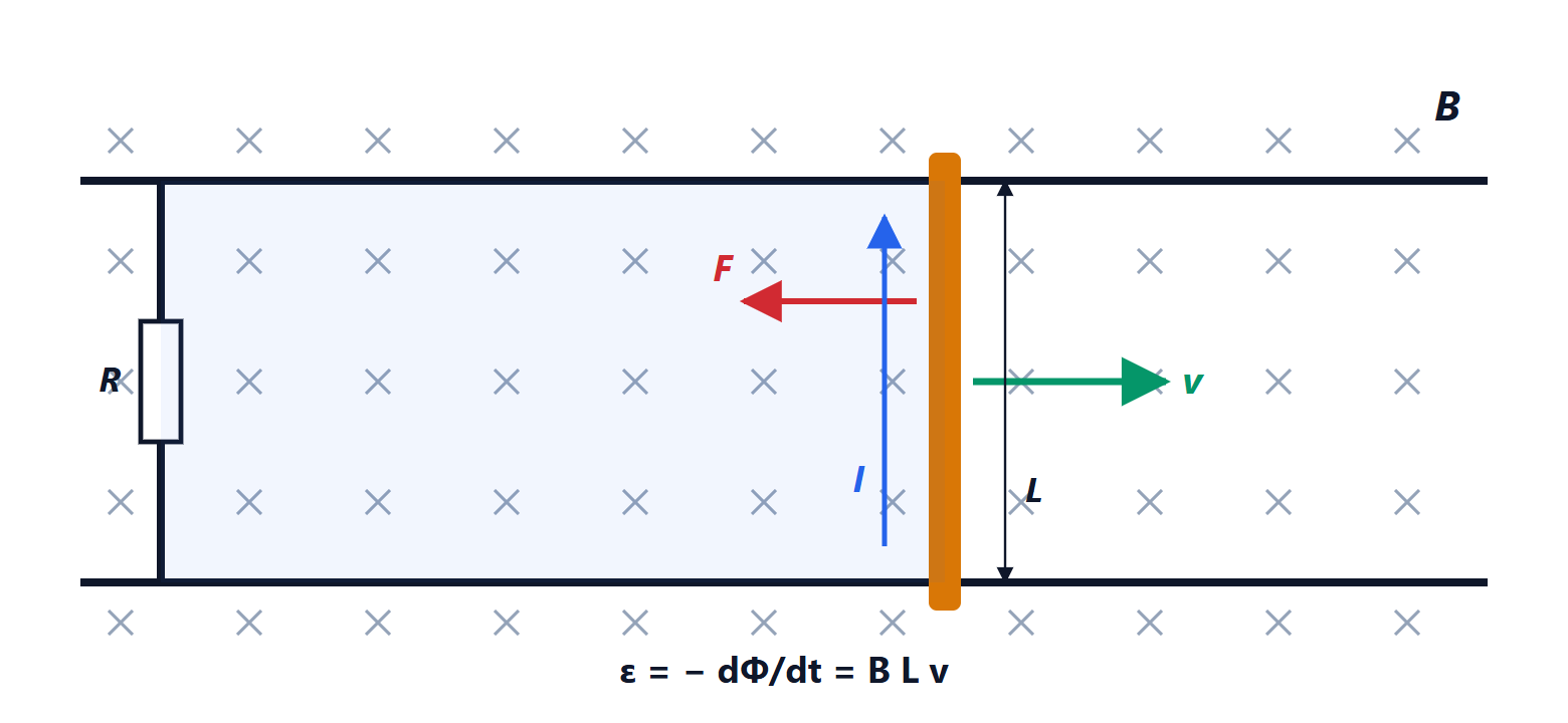
Proof with the Lorentz force
The electrons in the bar move at speed  in the field and feel the Lorentz force, directed along the bar: it is as if there were a source inside the bar. The work per unit charge along the bar is
 . With Faraday’s law: the circuit’s area grows by
 per second, so

The same result. The current  in the bar feels the force
 , opposite to the velocity (Lenz). To keep the bar moving you must push it with power
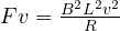 , which is exactly the power
 dissipated in the resistor: mechanical energy becomes electrical energy. It is an elementary generator.
The AC generator
A coil of turns and area rotating at angular velocity  in a uniform field has flux
 , and therefore

a sinusoidal voltage. It is the principle of the alternators in power stations, cars and wind turbines. In Europe the turbines spin so that the frequency is 50 Hz.
The transformer
Two coils wound on the same iron core share the same flux. If an alternating voltage is applied to the primary, with  turns, the secondary, with
 turns, gets

and in an ideal, lossless transformer  : if the voltage goes up the current goes down. It works only with AC, because a changing flux is needed. Modern switching power supplies work at tens or hundreds of kilohertz instead of 50 Hz: for the same power the core can be much smaller, because the voltage induced per turn grows with frequency.
Eddy currents
A changing field also induces currents inside solid conductors: eddy currents. They dissipate energy as heat, which is why transformer cores are made of insulated laminations, or of non-conducting ferrite. But they can also be put to use: induction hobs heat the pan exactly this way, and eddy current brakes slow trains and roller coasters without contact.
Self-inductance and the RL circuit
A changing current in a coil changes its own flux,  , and induces in the coil itself the voltage
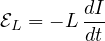
which opposes the change in current. Inductance is the “inertia” of current: just as mass resists changes in velocity, inductance resists changes in current.
In a circuit with resistance  and inductance
 connected to a source
 , the loop law gives
 , and

the same form as a charging capacitor, with the roles swapped: at first the inductor behaves like an open circuit, in steady state like a short circuit.
Beware of overvoltages. If the current in an inductor is interrupted suddenly,  becomes huge and so does the induced voltage: it is the spark you see when unplugging a vacuum cleaner. Circuits that drive relays or motors with a transistor always have a flyback diode across the coil, giving the current a path while it dies away. The same effect, under control, is the principle of a car’s ignition coil and of boost converters, which produce voltages higher than their input.