Sources of the magnetic field: Biot-Savart, Ampère's law and the solenoid
The Biot-Savart law, field of a wire and a loop, force between two wires, Ampère's law, the solenoid field with proof, electromagnets and inductance.
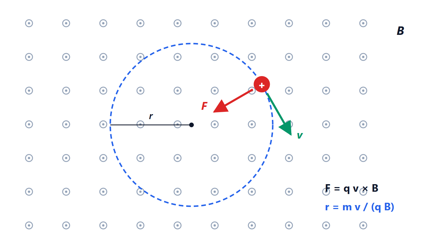
In the previous lesson the magnetic field was given. Here we ask where it comes from: the sources of the magnetic field are currents. We cover the Biot-Savart law, the field of a wire and of a loop, the force between two wires, Ampère’s law and the solenoid, up to the inductance we will use in the lesson on induction.
The Biot-Savart law
A wire element  carrying current
 produces, at a point a distance
 away, the field
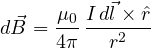
where  T·m/A is the permeability of free space (since 2019 its value is measured rather than fixed, but it is the same to within one part in a billion). It is the counterpart of Coulomb’s law, with two differences: the source is a current element, not a charge, and the field is perpendicular to both and
 .
The field of a straight wire
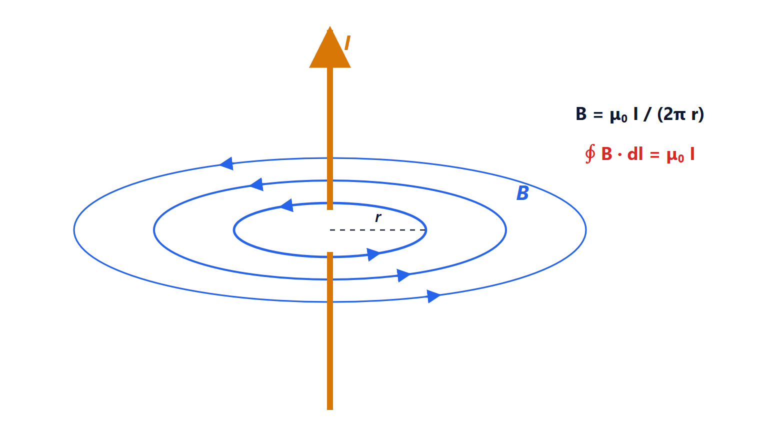
Integrating Biot-Savart over an infinite wire (or, faster, with Ampère’s law below):

At 1 cm from a wire carrying 10 A the field is  mT, four times the Earth’s field: enough to deflect a compass, as Ørsted saw.
At the centre of a circular loop of radius  : each element is perpendicular to the radius and contributes along the axis, so
 .
The force between two wires and the definition of the ampere
Two parallel wires a distance  apart, carrying
 and
 : wire 1 creates at wire 2 the field
 , and wire 2 feels the force
 . The force per unit length is
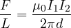
attractive if the currents flow the same way, repulsive if opposite. With 1 A in each wire 1 m apart the force is  N/m: the old definition of the ampere. In short circuits these forces become huge: with tens of thousands of amperes, the busbars in switchboards must be braced to withstand forces of tonnes.
Ampère’s law
The circulation of the magnetic field around a closed line equals  times the enclosed current:
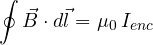
It checks out at once on the wire: around a circle of radius ,  is constant and tangent, so
 . It plays the role Gauss’s law plays for the electric field: it always holds (for steady currents), but it helps compute the field only when there is symmetry. It is also the counterexample of Analysis 2: the wire’s field is irrotational outside the wire, but not conservative, because there is a “hole” where the current flows. In local form:
 .
The solenoid
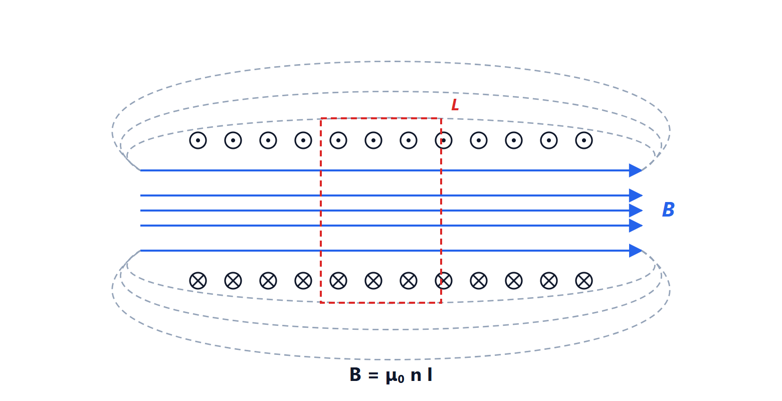
A solenoid is a wire wound as a helix with  turns per unit length. Inside, the fields of the turns add up and the field is nearly uniform and parallel to the axis; outside it almost vanishes.
Proof
Apply Ampère’s law to the rectangle in the figure, with one side of length  inside the solenoid and one outside. Outside
 ; on the sides perpendicular to the axis
 : only the inside side remains,
 . The enclosed current is that of the
 turns crossed,
 . So

independent of position inside the solenoid. With 1000 turns per metre and 1 A,  mT. With an iron core, whose relative permeability
 is in the thousands, the field grows by the same factor: the electromagnet of relays, solenoid valves and electric locks.
Inductance
The magnetic flux linked with a circuit is proportional to its current. The constant of proportionality is the inductance:

For a solenoid of  turns, length
 and cross-section
 : the flux through one turn is
 , the flux linked with all
 turns is
 , so
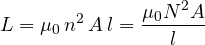
Inductance grows with the square of the number of turns. Just as a capacitor stores energy in the electric field, an inductor stores it in the magnetic field, with energy  and density
 . In the next lesson we will see what happens when the current changes: that is where inductance takes centre stage.