Anisotropic media: the Polder tensor of ferrite, birefringent crystals, ionospheric plasma and the Hall effect
Permeability, permittivity and conductivity tensors derived from the physics of the material: Polder tensor proved, Faraday rotation, isolators and circulators, wave plates, plasma frequency and Faraday rotation in the ionosphere, Hall effect.
In the materials seen so far the response to the field is a scalar:  ,
 ,
 , and the response vector is parallel to the field that produces it. In many important materials this is not so: a field along
 also produces a response along
 . The constant then becomes a 3×3 matrix, a tensor, and the medium is called anisotropic. Devices without which radar, telephony and optics would not work rely on this: ferrite isolators and circulators, wave plates and polarisers, Hall-effect sensors, and the choice of circular polarisation in satellite links. This lesson derives the four main tensors from the physics of the material: the permeability of ferrite (Polder tensor), the permittivity of crystals, that of magnetised plasma (the ionosphere) and the conductivity in a magnetic field (Hall effect). The linked exercises show how they are used.
What a tensor is in electromagnetism
A second-order tensor is a matrix that turns a vector into another vector:  . The element
 says how much field along produces electric displacement along . Changing the reference frame with a rotation
 , the matrix changes as
 : its numbers depend on the chosen axes, but the physical link between the vectors does not.
Two properties decide everything that follows.
- If the tensor is real and symmetric (lossless crystals), by the spectral theorem there are three perpendicular axes, the principal axes, in which the matrix is diagonal: along each the medium behaves like an isotropic medium, with its own constant. Waves polarised along different axes travel at different speeds.
- If the tensor is Hermitian but not symmetric, with imaginary and opposite off-diagonal elements (magnetised ferrites and plasmas: gyrotropic media), the “proper” axes are complex: they are the circular polarisations. The two circular polarisations travel at different speeds, and the medium is non-reciprocal.
Ferrite: the Polder tensor
Ferrites (iron oxides with other metals, such as yttrium iron garnet YIG) are magnetic but insulating: microwaves pass through them without being reflected as by a metal. Each electron has a magnetic moment linked to its spin, and in a static magnetic field  the magnetisation
 does not align with the field at once: it precesses around it, like a tilted spinning top around the vertical. The equation of motion (Landau-Lifshitz, without damping) is
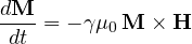
with  rad/(s·T), the gyromagnetic ratio of the electron (
 GHz/T).
Theorem (Polder tensor). With a ferrite saturated by a static field  (magnetisation
 ) and a small microwave field
 ,
 with

where  is the angular frequency of ferromagnetic resonance and
 .
Proof. Write  ,
 , substitute and neglect products of two small terms (
 ); the term
 is zero. What remains is

In components, with  and
 :

A 2×2 linear system in  , with determinant
 . By Cramer’s rule:

and  . Finally
 : collecting the coefficients of
 and
 gives the matrix of the statement. ∎
The  term is the signature of precession: a microwave field along produces a magnetisation along , 90° out of phase. The tensor is Hermitian (
 ) but not symmetric: the lossless ferrite does not absorb energy, but it is not reciprocal.
The two circular waves. The eigenvectors of the transverse part are  , the two circular polarisations, with eigenvalues

(the check is immediate:  = (\mu + \kappa)(\hat x - j\hat y)](https://www.electronics-engineering.com/wp-content/ql-cache/quicklatex.com-57928aa58ffbcbd23d77fcb6a3762f6c_l3.png "Rendered by QuickLaTeX.com") ). A plane wave travelling along
 , parallel to the static field, therefore sees two different media depending on the sense of rotation of its field:
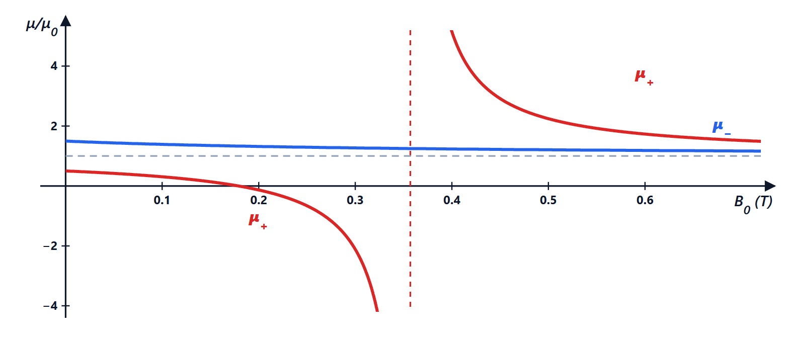
 . For the wave rotating in the same sense as the precession,
 becomes infinite at resonance
 : with real losses, that wave is absorbed.
Faraday rotation, isolators and circulators
A linearly polarised wave is the sum of two opposite circular waves. In the ferrite they travel with different phase constants, and after a length  the phase difference between them rotates the plane of polarisation by

This is Faraday rotation. The decisive point is that the sense of rotation is fixed by the static field , not by the direction of propagation: a wave going back is not “unwound”, but rotates again in the same sense with respect to . There and back, the rotation doubles. It is the opposite of what happens in a sugar solution (optical activity), where there and back cancel.
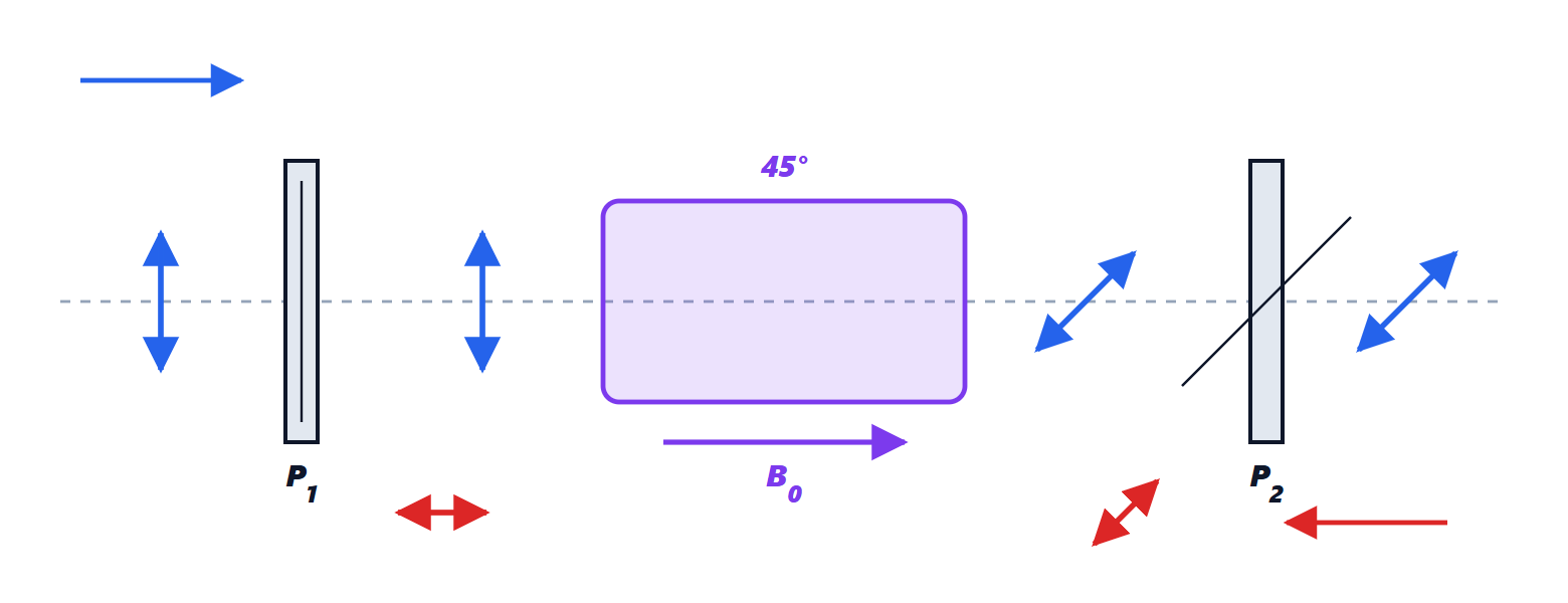
The isolator is built on this: a 45° rotator between two polarisers inclined at 45° to each other. The forward wave rotates by 45° and passes; the reflected wave comes back, rotates by another 45° and arrives perpendicular to the first polariser, which absorbs it. This protects a transmitter (a magnetron, an amplifier) from the reflections of a mismatched load.
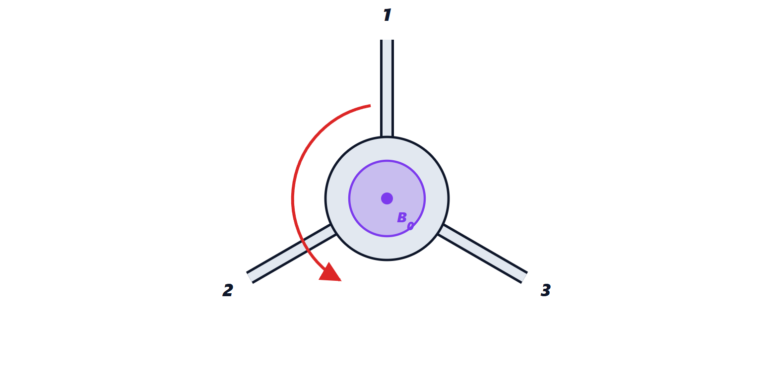
The circulator is the three-port generalisation: what enters port 1 leaves from 2, what enters 2 leaves from 3, what enters 3 leaves from 1. In a single-antenna radar it connects transmitter, antenna and receiver: the pulse goes to the antenna, the echo comes back to the receiver. Its scattering matrix is
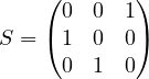
Theorem. A lossless, three-port network matched at all ports and reciprocal does not exist: the circulator, which is lossless and matched, must be non-reciprocal (and therefore contain a magnetised ferrite, or active electronics).
Proof. Reciprocal means  symmetric; matched, zero diagonal:
 . Lossless means unitary: orthonormal columns. Orthogonality of the columns two by two gives
 ,
 ,
 : at least two of
 are zero. But normalisation requires
 ,
 ,
 : with two coefficients zero one of these becomes
 . ∎
Crystals: the permittivity tensor
In a crystal the atoms are arranged in a lattice, and electrons move more easily in some directions than in others:  .
Theorem. In a lossless medium the permittivity tensor is real and symmetric, so there are three perpendicular principal axes.
Proof. The stored energy per unit volume increases by  . For
 to be a function of state (not depending on the path by which the final field is reached, otherwise a closed cycle would create or destroy energy) the differential form must be exact:
 must equal
 . A real symmetric matrix can be diagonalised by a rotation (spectral theorem). ∎
In the principal axes  . In uniaxial crystals (quartz, calcite, lithium niobate) two indices are equal:
 (ordinary index) and
 (extraordinary); the
 axis is the optic axis. A wave travelling perpendicular to the optic axis splits into two waves: with the field perpendicular to the axis it travels at
 , with the field parallel at
 . This is birefringence: looking through a calcite crystal (
 ,
 ) one sees a double image.
Wave plates. A plate of thickness  cut parallel to the optic axis introduces between the two components a phase difference
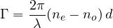
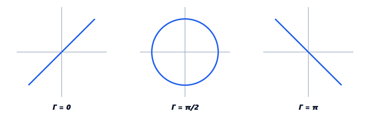
With  (quarter-wave plate) linear light at 45° to the axes comes out circularly polarised; with
 (half-wave) linear light rotates by twice the angle it makes with the axis. In Jones calculus a plate with its slow axis at angle
 is the matrix
 , with the rotation: the exercises use it. The same ideas, with lithium niobate in which
 depends on the applied electric field (electro-optic effect), give the 100 Gbit/s optical fibre modulators.
Magnetised plasma: the ionosphere
The ionosphere, between 60 and 1000 km altitude, contains free electrons (up to about  per cubic metre) immersed in the Earth’s magnetic field
 (about 50 μT). An electron of charge
 and mass
 obeys
 : the same structure as the precession in ferrite, with the cyclotron angular frequency
 instead of
 . The current
 gives the plasma a permittivity tensor of the same gyrotropic type.
For waves travelling along there are again two circular waves, with indices

( is the plasma angular frequency). Without a magnetic field (
 ) what remains is
 : below the plasma frequency the index is imaginary and the wave is reflected. With
 m⁻³ the plasma frequency is about 9 MHz: this is why short waves (HF) bounce off the ionosphere and travel around the world, while FM, TV and satellites pass through it.
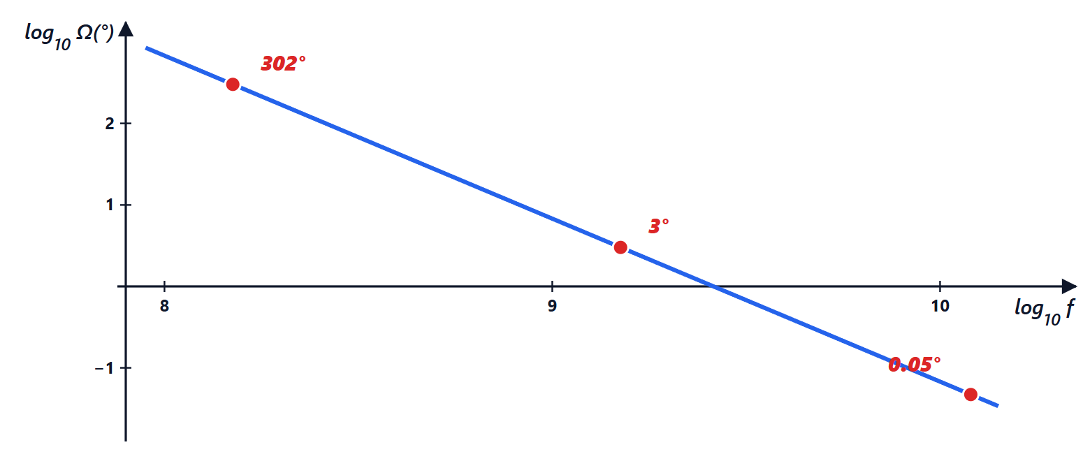
Theorem (Faraday rotation in the ionosphere). For  a linear wave crossing the ionosphere along rotates by

where  is the total electron content (electrons per square metre along the path).
Proof. With  :
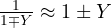 ,
 ,
 . The difference between the indices is
 , and as for ferrite the rotation is half the phase difference:
 . With
 the formula follows. ∎
With a typical TEC of  m⁻² the rotation is 302° at 150 MHz, 3° at 1.5 GHz and 0.05° at 12 GHz (the exact calculation with the complete indices gives the same values within 0.2 %). TEC changes during the day and with solar activity, so the rotation at VHF is unpredictable: a linear ground antenna can end up crossed with the received wave. This is why low-frequency satellites (GPS at 1.2-1.6 GHz, VHF telemetry) use circular polarisation, which Faraday rotation does not alter.
The conductivity tensor: the Hall effect
In the Drude model a conduction electron accelerates in the field and loses its velocity in collisions, on average every  :
 . In steady state, with
 and , a 2×2 system is solved as for ferrite:

(the sign of the off-diagonal elements depends on the sign of the carriers). More useful is the inverse tensor, the resistivity:

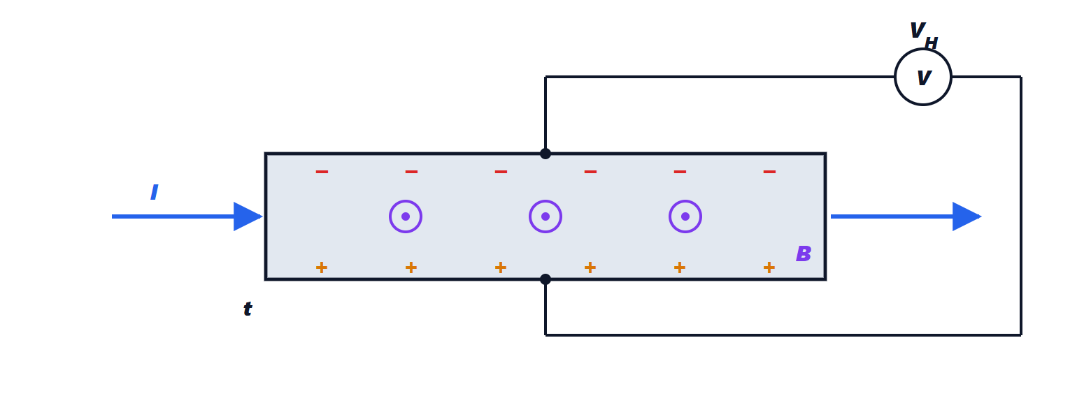
Two surprising results in one line. The resistance along the current does not depend on the magnetic field (the Drude model has no magnetoresistance). And the transverse resistivity  does not depend on , i.e. on collisions: it directly measures the carrier density and its sign. In a bar of thickness
 carrying current
 a Hall voltage
 appears. In copper it is tiny (less than a microvolt with 1 A and 1 T); in a lightly doped semiconductor, with
 millions of times smaller, it reaches millivolts even with currents of 1 mA. These are Hall sensors: contactless current sensors, brushless motor encoders, ABS wheel speed sensors.
Summary
| medium | tensor | form | effect | devices |
|---|---|---|---|---|
| magnetised ferrite |  | Hermitian,  off diagonal | Faraday rotation, non-reciprocity | isolators, circulators, phase shifters |
| crystal |  | real symmetric | birefringence | wave plates, polarisers, modulators |
| magnetised plasma | | Hermitian, like ferrite | reflection below  , Faraday rotation | HF links, choice of polarisation |
conductor in field  |  | antisymmetric off diagonal | Hall effect | Hall sensors |
The mathematical structure is always the same: a linear equation of motion for charges or spins, a 2×2 system in the plane perpendicular to the static field, circular eigenvectors when a magnetic field breaks the symmetry between the two senses of rotation.