Rectangular waveguides: the TE10 mode and cut-off frequency
Two bouncing plane waves, the TE10 mode with proof, cut-off frequency and single-mode band, the WR-90 guide, phase and group velocity, dielectric guides and cavities.
Above a few gigahertz coaxial cables become very lossy and handle little power. For radars, radio links and satellite transmitters waveguides are used instead: hollow metal tubes, usually of rectangular cross-section, in which the wave travels by bouncing off the walls. Unlike two-conductor lines, a waveguide has a cut-off frequency: below it, nothing is transmitted. In this lesson we derive the fundamental mode of the rectangular waveguide and its properties.
The idea: two bouncing plane waves
Picture two parallel metal walls a distance  apart. A plane wave travelling at an angle
 to the guide axis is reflected by the walls, and the sum of the two waves, the one going up and the one coming down, forms a standing wave across the guide and a travelling wave along it. The electric field tangential to the walls must vanish (perfect conductor): this is possible only if a whole number of “transverse” half-wavelengths fits in the width . The lower the frequency, the more steeply the wave must tilt to meet this condition, until it bounces perpendicular to the walls without moving forward: this is cut-off.
The TE10 mode
Theorem. In a rectangular waveguide with sides  and perfectly conducting walls there is the solution

with  .
Proof. The field must satisfy the Helmholtz equation  . Substituting the proposed form, the second derivative in
 gives
 , the one in
 gives
 , the one in
 zero:
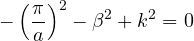
which is the relation for  . The boundary conditions are met:
 is tangential to the walls
 and
 and vanishes there thanks to the sine; on the walls
 and
 it is normal, which is allowed. The magnetic field follows from Faraday’s law. ∎
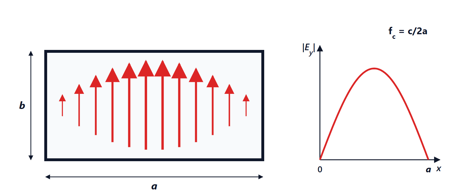
It is called TE10 (transverse electric, with one half-wave across and none across  ) and it is the fundamental mode, the one with the lowest cut-off frequency.
The cut-off frequency
For the wave to propagate, must be real, that is  . The cut-off frequency, in air, is

Below  , becomes imaginary and the field decays exponentially along the guide without carrying power. A waveguide thus behaves as a high-pass filter: this is also the principle of the metal mesh in a microwave oven door, whose holes are too small for 2.45 GHz waves to pass.
In general the TE modes have cut-off frequency
 , and the guide is designed to be used in the band where only TE10 propagates, between and the cut-off of the next mode, so that energy is not split among modes with different velocities.
Example. The standard WR-90 waveguide has  mm and
 mm. TE10 has
 GHz; TE20 is at 13.1 GHz and TE01 at 14.8 GHz. The recommended operating band is 8.2 to 12.4 GHz, the radar “X band”.
Phase and group velocity
The guide wavelength,  , is longer than in free space:
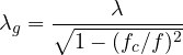
At 10 GHz in WR-90,  cm but
 cm. Consequently the phase velocity
 is greater than
 , while the group velocity, at which energy and information travel, is smaller:

In the example  . A phase velocity above does not violate relativity: it is the speed at which the “pattern” of crests moves along the guide, like the point where a sea wave meets the shore, which can run faster than the wave itself. The dependence of velocity on frequency (dispersion) distorts short pulses, and must be accounted for in radars.
Dielectric guides and cavities
- Dielectric waveguides, such as optical fibres, confine the wave by total internal reflection instead of metal walls; they too have modes and cut-off frequencies, and a single-mode fibre is designed so that above a certain wavelength only one mode propagates.
- Closing a waveguide at both ends gives a resonant cavity: standing waves can exist only at precise frequencies, with quality factors of tens of thousands. Cavities are the filters of cellular base stations and the heart of microwave-oven magnetrons and particle accelerators.