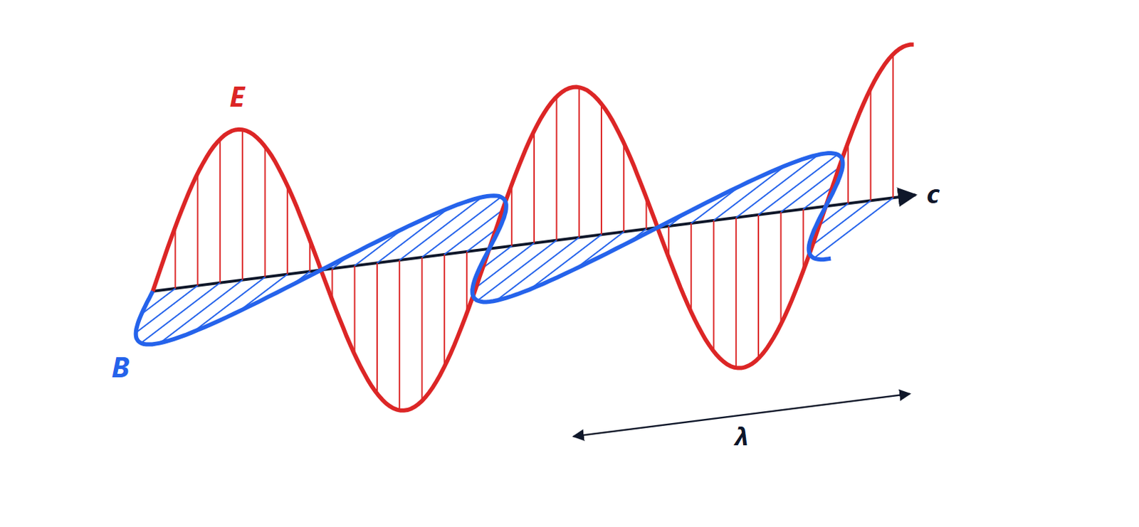
Antennas: gain, effective area, the Friis formula and arrays
Antenna parameters, reciprocity and effective area, the Friis formula with proof and link budget with examples, the array factor and phased arrays.
An antenna turns a current into a wave and vice versa. To design a radio link you do not need to solve Maxwell’s equations every time: a few parameters describing the antenna from the outside are enough, together with a formula that says how much power reaches the receiver. In this lesson we cover antenna parameters, effective area, the Friis formula for the link budget and antenna arrays, which make it possible to steer the beam electronically.
Antenna parameters
- Radiation pattern: how the radiated power is distributed over directions. It is described by the main lobe, its half-power beamwidth (the angle within which the power is at least half the maximum) and the side lobes.
- Directivity
 : the ratio of the maximum radiation intensity to that of an isotropic antenna radiating the same total power.
- Gain
 : directivity multiplied by the efficiency
 , the fraction of the input power actually radiated. It is expressed in dBi (decibels relative to isotropic).
- Input impedance: it must be matched to the line feeding the antenna.
- Polarisation and bandwidth, the frequency range over which the parameters remain acceptable.
Some typical values: half-wave dipole 2.15 dBi, Wi-Fi router antenna 2 to 5 dBi, cellular base station panel antenna 15 to 18 dBi, one-metre satellite dish at 12 GHz about 40 dBi.
Reciprocity and effective area
By the reciprocity theorem, an antenna has the same pattern and the same gain in transmission and in reception. In reception the effective area  is used: the power received from a wave with power density
 (in W/m²) is
 , as if the antenna “collected” the wave over that area. Effective area and gain are related by

a general relation, valid for any antenna. For a half-wave dipole at 100 MHz ( m),
 m², much more than its geometric cross-section. For a dish the effective area is 55 to 70% of the aperture area, hence
 : a one-metre dish at 12 GHz has a gain of about 9500, that is 40 dBi.
The Friis formula
Theorem. Two antennas with gains  and
 , at a distance
 much larger than their size and the wavelength, in free space and with matched polarisations:
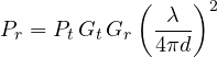
Proof. An isotropic antenna radiating  spreads the power over a sphere of area
 ; with gain , in the direction of the receiver the power density is
 . The receiving antenna collects
 , which is the formula. ∎
The term  is the free-space path loss. In decibels the formula becomes a sum, the link budget:

Examples.
- Wi-Fi at 2.4 GHz, 100 m, 20 dBm (100 mW) of power, 2 dBi antennas: the free-space path loss is 80 dB and
 dBm, an excellent signal (receivers work down to about −90 dBm). Inside a building walls take away much more.
- Geostationary satellite at 36 000 km, 12 GHz: free-space path loss of about 205 dB. That is why dishes with tens of dBi of gain are needed on the ground and on the satellite.
The received power falls as  : doubling the distance costs 6 dB. The factor
 does not mean that high frequencies “attenuate more” in space: for the same gain, antennas are smaller and collect less; for the same antenna size, gain grows with frequency and the link actually improves.
Antenna arrays
Placing several identical antennas in a row and feeding them together, their fields add with phases that depend on direction. The array pattern is that of the single element multiplied by the array factor. For  elements spaced , fed with equal amplitude and a progressive phase shift
 from one element to the next:

(obtained by summing the geometric series  , as for the moving average in digital filters).
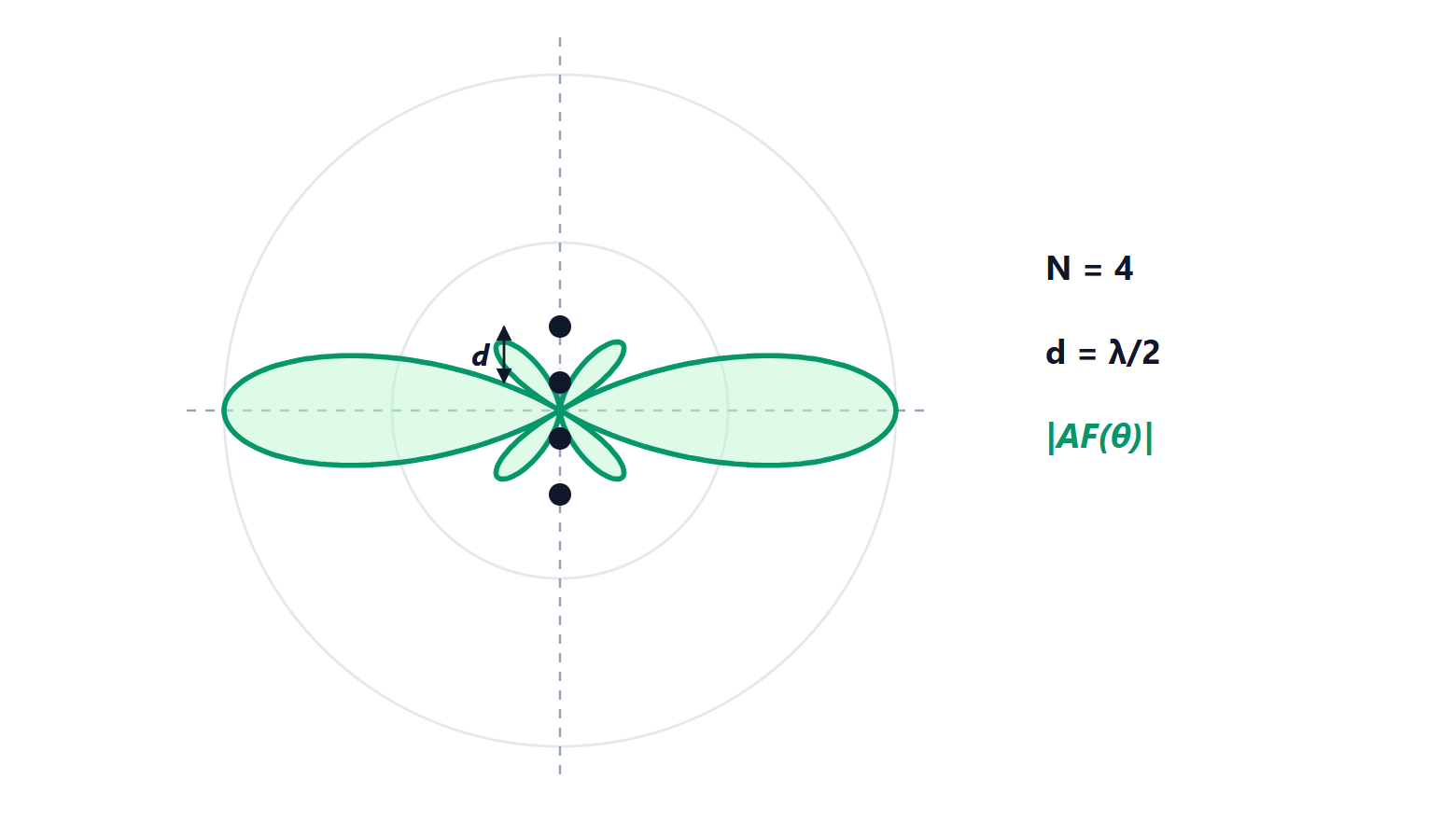
- With
 the beam is perpendicular to the array (broadside), and with elements it becomes about times narrower: cellular base station antennas are columns of dipoles that concentrate power towards the horizon.
- By varying electronically the beam steers with no moving parts: this is the phased array, used in military and weather radars, in the antennas of low-orbit Internet satellites and in 5G, where the base station points a different beam at each user.
- With
 other lobes as strong as the main one appear (grating lobes), the same phenomenon as aliasing in sampling: the array “samples” the field in space, and at least one element every half wavelength is needed.