Antenna temperature, G/T and antenna measurements
Brightness and antenna temperature, system temperature and the G/T figure of merit with an example, anechoic chambers and compact ranges, near-field measurements, the three-antenna method proved, efficiency.
An antenna does not receive only the signal: it also receives the thermal noise of everything it “sees”, the sky, the ground, the Sun. And a designed antenna must be measured, which is less simple than it seems, because the measurement itself involves other antennas and the surrounding space. In this lesson we look at antenna temperature, system temperature and the G/T figure of merit with an example, anechoic chambers and measurement ranges, near-field measurements, and the three-antenna method for gain with its proof.
Antenna temperature
Every body at temperature  emits thermal noise (Electrical Communications lesson on receiver noise). An antenna pointed at an absorbing body at temperature delivers to the receiver a noise power
 , like a resistor at that temperature. In general the antenna sees regions at different temperatures, weighted by its pattern: the antenna temperature is the average of the brightness temperature of sky and ground, weighted by the radiation pattern,
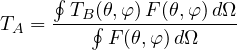
The clear sky between 1 and 10 GHz, looking towards the zenith, is extremely cold: a few kelvin, the cosmic background plus a little atmosphere. The ground is at about 290 K. A dish pointed at a satellite sees mostly cold sky, but the side lobes and the spillover (lesson on apertures) pick up some warm ground: typical values of  are 20-50 K. Pointed at the Sun, the antenna temperature rises to tens of thousands of kelvin, and the link drops for a few minutes: this is the sun outage that satellite operators predict twice a year.
System temperature and G/T
To the antenna noise is added that of the receiver, described by its equivalent temperature  . The system temperature is
 , and the signal-to-noise ratio of a link is proportional to

the figure of merit of a receiving station, expressed in dB/K: doubling the gain or halving the system temperature has the same effect.
Example. The 35.5 dBi dish of the lesson on apertures, with  K and a low-noise converter with
 K (noise figure about 0.7 dB):
 K, i.e. 19 dBK, and
 dB/K. That is why in low-noise receiving antennas the amplifier mounted at the focus matters so much: with a 290 K receiver almost 6 dB would be lost.
Where an antenna is measured
To measure the pattern one must be in the far field, beyond  (lesson on the far field), and with no reflections adding to the direct field. The solutions are:
- outdoor ranges, with the antennas on tall towers to keep the ground away, used for large antennas at low frequencies;
- anechoic chambers: shielded rooms lined with pyramids of absorbing material, which reflect less than a thousandth of the incident power. The antenna under test rotates on a positioner while a fixed antenna transmits, and the received power is recorded as a function of angle;
- compact ranges: a large parabolic reflector turns the spherical wave of a nearby source into a plane wave in a test zone, simulating the far field in a few metres;
- near-field measurements: a small probe scans the field over a plane or a cylinder a few wavelengths from the antenna, in amplitude and phase, and the far field is computed with the spatial Fourier transform (the same relation between aperture and pattern as in the lesson on apertures). It is the method used for the large arrays of radars and satellites.
Impedance and matching are measured instead with a vector network analyser, which measures the reflection coefficient  as a function of frequency: the antenna’s bandwidth is the range in which
 stays below −10 dB.
Measuring gain
The most common method is comparison: the received power is measured with the antenna under test and with a standard gain antenna of known gain, typically a horn (lesson on apertures), in the same position. The ratio of the powers gives the ratio of the gains. But how is the gain of the standard antenna known accurately, without yet another standard antenna? With the three-antenna method, which needs none.
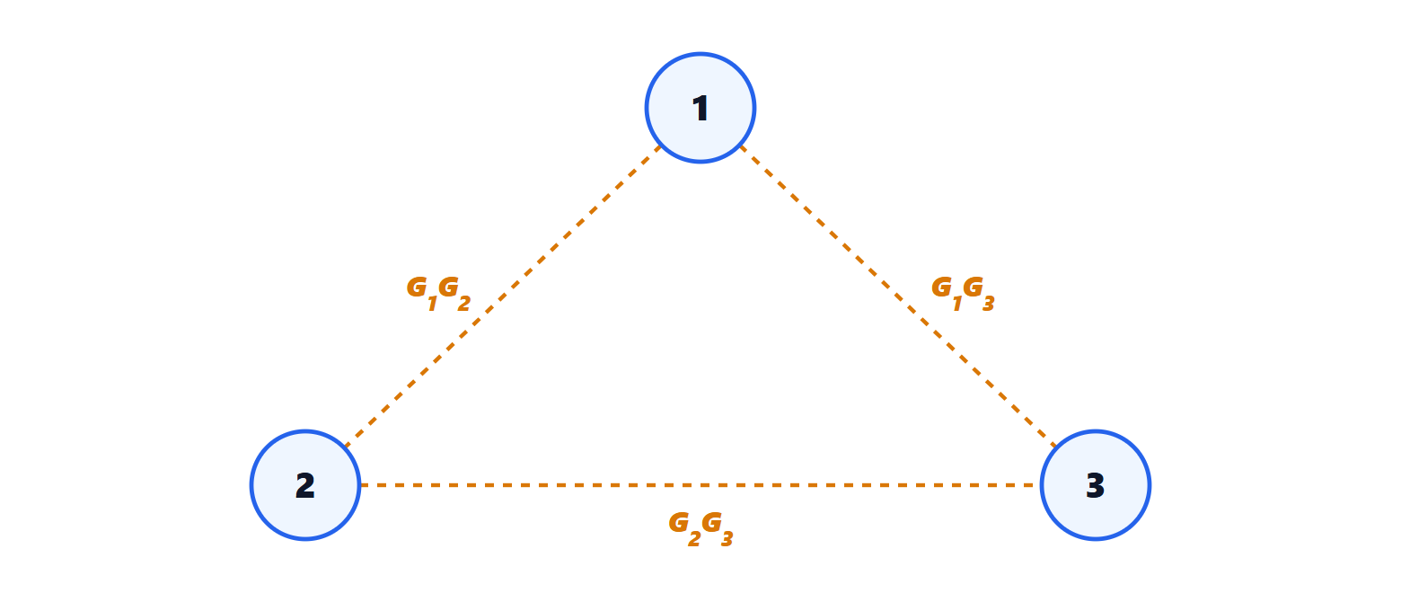
Theorem. Measuring in pairs, at distance  , the three link losses between three antennas, and setting
 , the gains in dB are
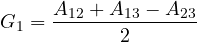
and similarly for  and
 .
Proof. By the Friis formula, in dB,  , so
 . The three measurements give the linear system
 ,
 ,
 . Adding the first two and subtracting the third:
 . ∎
The method requires only relative power measurements, a known distance and frequency, and matched antennas with the same polarisation, and it is the basis of gain calibrations in metrology laboratories, with uncertainties of a few hundredths of a decibel.
Efficiency
The radiation efficiency of small antennas, such as those of wearable devices, is measured with the Wheeler method: the input resistance of the antenna in free space is compared with that of the antenna enclosed in a small metal box, which prevents radiation while leaving the losses. Or the total radiated power is measured directly in a reverberation chamber, a metal room with reflecting walls and a stirrer that mixes the field: the exact opposite of the anechoic chamber.