Half-wave dipole, monopole, folded dipole and Yagi antenna
Current on the dipole, field of the half-wave dipole with proof, 73-ohm resistance and directivity, shortening, the monopole with the image theorem, the folded dipole, baluns, the Yagi-Uda antenna.
The half-wave dipole is the reference antenna of radio engineering: simple, easy to match, with a well-known pattern, and the basis of many more complex antennas. In this lesson we compute its field with the vector potential integral, deriving the pattern with proof, look at radiation resistance, directivity and shortening, the monopole over a ground plane with the image theorem, the folded dipole, baluns and the Yagi-Uda antenna.
The current on a dipole
A dipole is a straight conductor broken at the centre, where the source is connected. If it is thin, the current along the wire has, to a good approximation, the shape of a standing wave, zero at the ends (Electromagnetic Fields lesson on standing waves). For a dipole  long, extending from
 to
 :

The field of the half-wave dipole
Theorem. The far field of the half-wave dipole is

Proof. Each segment  is a short dipole giving, at distance
 , the contribution of the lesson on the far field,
 , where the last factor is the path difference of the segment with respect to the centre. Integrating, with
 , what remains to compute is

(the part with the sine is odd and vanishes). With  and
 , the integral equals
 . Both sines equal
 , and the sum is
 . Multiplying by
 gives the result. ∎
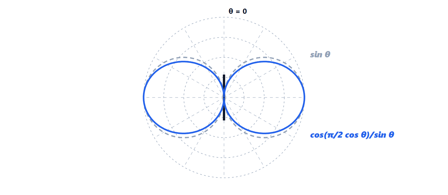
The pattern resembles that of the short dipole,  , but is slightly narrower: the half-power width drops from 90° to 78°.
Resistance, directivity and shortening
Integrating the power over all directions (a numerical calculation) gives

against 1.5 (1.76 dBi) for the short dipole. The 73 Ω resistance matches 50 or 75 Ω coaxial cables well. A dipole exactly long, however, has an input reactance of about  ; shortening it by 3-5 %, depending on its thickness, makes it resonant and the resistance drops to about 70 Ω. The gain of radio systems is often given in dBd, relative to the dipole: 0 dBd = 2.15 dBi.
The monopole and images
A vertical antenna  long above a conducting plane (the monopole) is the antenna of cars, of medium-wave broadcast stations and of many portable radios.
Theorem (images). Above an infinite perfectly conducting plane, the field of a source equals that produced by the source and its mirror image, without the plane. For a vertical current the image has the same direction.
Idea of the proof. The problem with the plane has as boundary condition that the electric field tangent to the plane be zero. The source plus its mirror image produce, by symmetry, an electric field perpendicular to the plane of symmetry, hence with zero tangential component: it satisfies the same equation and the same condition in the upper half-space, and by uniqueness of the solution the field is the same. ∎
The monopole with its image therefore forms a half-wave dipole, and in the upper half-space it has the same field. But it radiates only into the upper half of space: for the same current the power is half, and the radiation resistance is half, 36.5 Ω. Directivity instead doubles, 3.28 (5.15 dBi), because the same maximum intensity is produced with half the power. In reality the ground plane is finite (the car body, four radials, the soil), and the pattern lifts somewhat off the horizon.
The folded dipole and baluns
The folded dipole is a narrow loop long: two parallel conductors joined at the ends, fed at the centre of one of them. It has the same pattern as the dipole, but the current splits between the two arms and the impedance seen at the terminals is four times larger, about 290 Ω: it suited the old 300 Ω television twin-lead. It also has a somewhat wider bandwidth.
The dipole is balanced (the two arms are symmetric with respect to ground), while coaxial cable is unbalanced (the shield is grounded). Connecting them directly, a current flows on the outer surface of the shield that radiates and distorts the pattern. The balun (balanced-unbalanced) is the transformer or transmission-line structure that acts as the interface, often also changing the impedance.
The Yagi-Uda antenna
Next to the driven dipole further conductors are placed that are not fed, called parasitic: a slightly longer reflector behind and a few slightly shorter directors in front, at spacings of  –
 . The currents induced on them, with suitable phases, reinforce radiation forwards and cancel it backwards: an array fed by coupling (lesson on arrays). With 3 elements about 7-8 dBi is obtained, with 10-15 elements 12-15 dBi. It is the classic rooftop television antenna, and it is still used by radio amateurs and in point-to-point links.