Interconnects: wire delay, repeaters, crosstalk and electromigration
Wire resistance and capacitance, delay quadratic in length proved, repeaters that make it linear proved, crosstalk and the Miller effect, supply drop, electromigration.
In the first integrated circuits interconnects were “free”: all the delay was in the transistors. With scaling, transistors became faster while wires became thinner and more resistive, and today in a large chip delay, power and most design problems lie in the interconnects. In this lesson we look at the resistance and capacitance of wires, the proof that the delay of a wire grows with the square of its length, repeaters with the proof that they make delay linear, crosstalk, supply drops and electromigration.
Resistance and capacitance of a wire
A copper wire of length  , width
 and thickness
 has resistance

In the lowest levels wires have cross-sections a few tens of nanometres on a side, and copper’s effective resistivity rises above its bulk value because electrons scatter off the surfaces and grain boundaries; moreover part of the cross-section is taken by the barrier that prevents copper from diffusing. A minimum wire can have hundreds of ohms per micrometre. The capacitance to neighbouring wires and to the layers above and below is about 0.1-0.2 fF per micrometre, almost independent of dimensions because width and spacings scale together.
The delay of a long wire
A wire is a distributed RC network: each segment has its own resistance and capacitance.
Theorem. The delay of a wire not driven by repeaters grows with the square of its length.
Proof. With resistance  and capacitance
 per unit length, divide the wire into
 segments, each with resistance
 and capacitance
 . By the Elmore delay (lesson on delays), the capacitance of segment
 is charged through resistances:
 , which for large tends to
 . In any case the delay is proportional to
 , because doubling the length doubles both the resistance and the capacitance. ∎
The more precise 50 % delay of a distributed line is  . A 1 mm wire with 100 Ω/µm and 0.2 fF/µm has
 ns: unacceptable in a processor working with 250 ps cycles.
Repeaters
The solution is to break the wire into segments, each driven by a repeater (an inverter or a buffer).
Theorem. With an optimal number of repeaters the delay of a wire becomes proportional to its length.
Proof. Each segment has length  and delay
 , where
 is the repeater delay and
 a constant. The total is
 . Differentiating with respect to and setting it to zero:
 , i.e.
 . Substituting, the two terms are equal and
 : proportional to . ∎
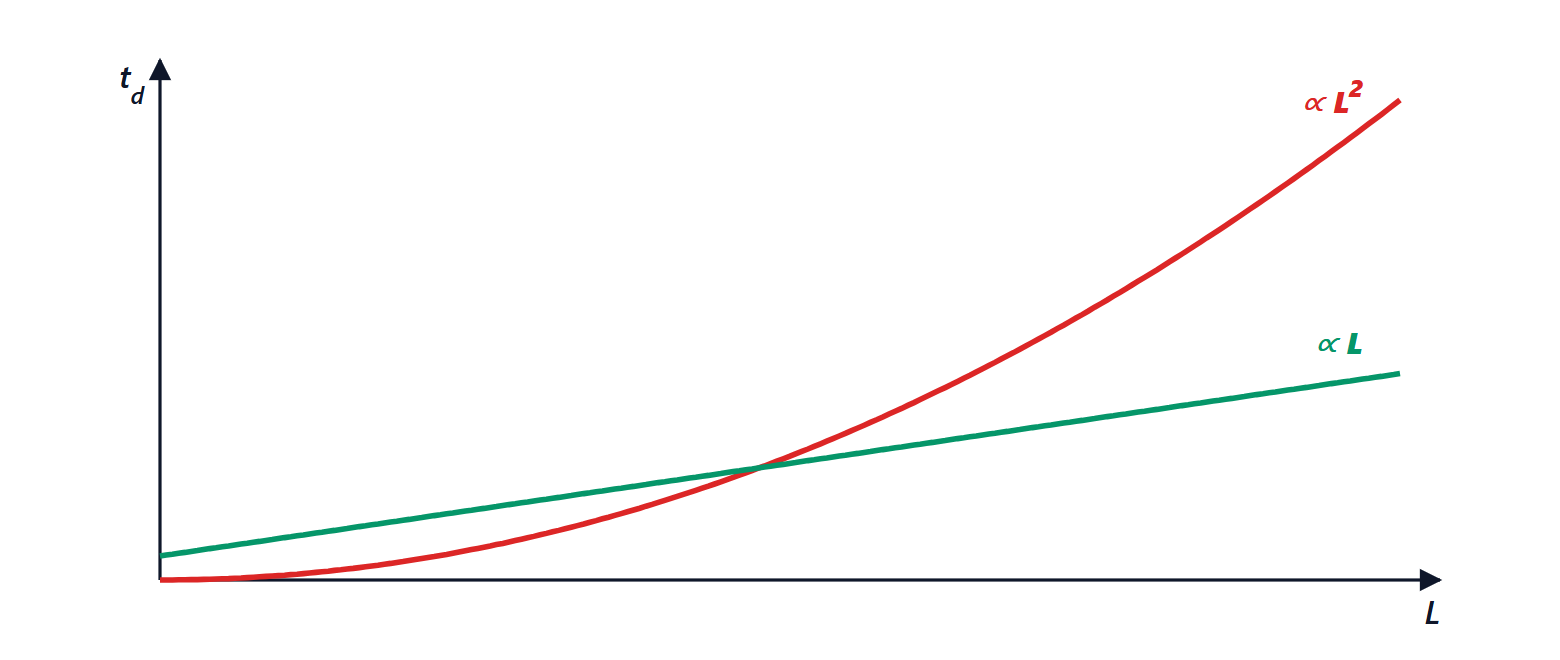
Modern processors contain millions of repeaters, which consume area and power. Long interconnects are routed in the upper metal levels, thicker and wider, with much lower resistance; and architectures are organised so that global signals are few, with data processed locally (Computer Architecture lesson on caches).
Crosstalk
Two close parallel wires form a capacitor: when one switches, it injects a disturbance into the other through the coupling capacitance, which in the lower levels is the largest part of the total capacitance. Two effects arise:
- noise on a quiet wire, which can exceed a gate’s threshold and cause an error;
- delay variations: if the neighbour switches in the opposite direction, the coupling capacitance sees twice the voltage change and it is as if it doubled (Miller effect); if it switches in the same direction, it is as if it vanished. The delay of a wire therefore depends on what its neighbours do, and timing analysis (lesson on the design flow) must take this into account.
It is fought by spacing critical wires, shielding them with ground wires, and alternating wire directions between one level and the next.
Supply and electromigration
The power network is also made of resistive wires: tens of amperes flowing through it produce voltage drops (IR drop), and rapidly changing currents produce inductive drops ( ) in the package. If the supply drops locally by 10 %, transistors slow down and timing no longer closes. Dense power grids, thousands of contacts with the package and on-chip decoupling capacitors are used.
Electromigration is the movement of metal atoms dragged by the flow of electrons at high current density: over the years voids form that break the wire and hillocks that short it to its neighbour. The mean lifetime follows Black’s law, inversely proportional to a power of the current density and decreasing exponentially with temperature. Design rules set the maximum current density in every wire.