Testing and reliability: faults, scan, built-in self-test
Stuck-at faults and ATPG, coverage and defect level with an example, scan chains, BIST and the LFSR period proved, the bathtub curve, ESD and latch-up.
Every chip produced must be tested: yield is never 100 % (lesson on the process), and a faulty chip that ends up in a car or a pacemaker can cost much more than the chip itself. But a circuit with billions of transistors cannot be tested on all input combinations: fault models and dedicated design structures are needed. In this lesson we look at the stuck-at fault model, coverage and the resulting quality with an example, scan chains, built-in self-test with linear feedback shift registers and the proof of their maximum period, and the main reliability mechanisms.
Fault models
A physical defect (a broken connection, a short between two wires) is represented by a logical fault model. The most widely used is the stuck-at fault: a circuit node stays fixed at 0 or 1. To detect it, it must be activated (driving the node to the opposite value) and propagated (making the difference reach an observable output). Automatic test pattern generation (ATPG) programs search, for each fault, an input combination that reveals it.
Coverage  is the fraction of modelled faults revealed by the test sequence. Delay fault models (a transition that is too slow) are also used, indispensable in modern processes where many defects slow a path down without blocking it.
Product quality
A chip that passes the test can still be faulty, if it has an uncovered defect. The fraction of faulty chips among those shipped is the defect level (DL), measured in parts per million. A classic model (Williams and Brown) relates it to the yield  and to coverage:

Example. With yield  : with 99 % coverage,
 , i.e. about 2200 ppm; with 99.9 %, about 220 ppm. The automotive industry asks for levels below 1 ppm: coverages extremely close to 100 % and several types of fault models are needed. Every extra decimal of coverage costs test time, and testers cost millions.
Scan chains
In a sequential circuit the internal state cannot be seen from outside nor imposed directly: generating tests would be prohibitive. The solution is design for testability (DFT) with scan chains: each flip-flop receives an input multiplexer that, in test mode, connects it to the previous flip-flop instead of the logic.
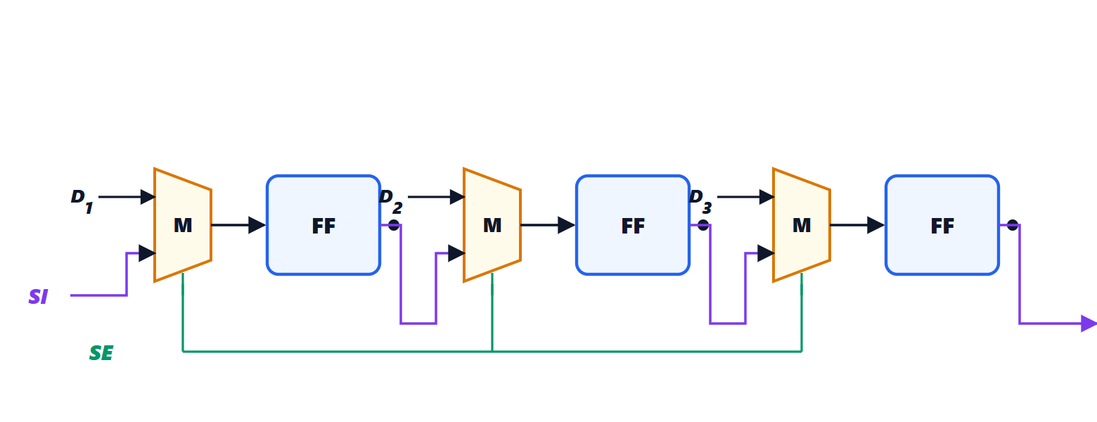
In test mode all the flip-flops form a long shift register: the desired state is shifted in serially, one clock is given in normal mode so that the combinational logic computes the new state, and it is shifted out serially to be compared with the expected one. The sequential problem becomes combinational, and ATPG reaches very high coverages. The price is a little area and delay for the multiplexers. To reduce test time many chains in parallel and compression of test data are used.
Built-in self-test
In BIST (built-in self-test) the chip tests itself: an internal generator produces the inputs, and a compactor summarises the outputs into a signature to be compared with the expected one. The most used generator is the linear feedback shift register (LFSR):  flip-flops in a row, with the input of the first equal to the XOR of some chosen outputs.
Theorem. An -bit LFSR has a period of at most  .
Proof. The state is the sequence of the bits, so there are  possible states. The all-zero state is a fixed point: the XOR of zeros is zero, and the register never leaves it. Starting from a non-zero state, the register can never reach zero: the update is linear and invertible (the previous state can be derived from the next one), and the zero state already has itself as predecessor. non-zero states remain; since each state determines the next, the sequence, after at most steps, must repeat a state and from then on it is periodic. ∎
With the feedback taps chosen according to a primitive polynomial the period is exactly : the register goes through all the non-zero states in a sequence with statistical properties similar to randomness. A 32-bit LFSR generates more than four billion different vectors with very little hardware. The same principle generates the pseudo-random sequences of spread-spectrum communications and CRC codes (Electrical Communications lessons). Memories have dedicated BIST, which writes and reads back patterns designed for their typical faults, and often spare rows and columns that replace faulty ones: repair greatly raises the yield of large memories.
Reliability
Once tested, the chip must work for years. The failure rate over time follows the bathtub curve: high at the start (early failures of weak chips), low and constant over the useful life, high again with wear-out. Early failures are fought with burn-in: chips intended for critical applications run for hours at high temperature and voltage, and the weak ones fail before shipment. The main wear-out mechanisms are electromigration in interconnects (lesson on interconnects), gate oxide degradation and transistor ageing, which slowly shifts thresholds.
Two risks concern inputs and outputs. Electrostatic discharges (ESD) from a person or a machine, thousands of volts, would destroy the extremely thin oxides: every pin has protection circuits with diodes and transistors that divert the discharge. Latch-up is the triggering of a parasitic thyristor formed by the doped regions of neighbouring n and p transistors, which short-circuits the supply; it is prevented with guard rings and frequent substrate contacts.