Aperture antennas: horns and the parabolic reflector
The equivalence principle, the uniform aperture and maximum directivity, aperture efficiency, horns as standard antennas, the paraboloid property proved, the gain of a dish with an example, offset and Cassegrain.
When gains of 30, 40 or 60 dBi are needed, as in satellite links, radio telescopes or microwave relays, aperture antennas are used: surfaces many wavelengths across through which the wave leaves as through a window. In this lesson we look at the equivalence principle, the pattern of a uniform aperture and its maximum directivity, aperture efficiency, horns, the geometric property of the paraboloid with its proof and the calculation of a dish’s gain.
The aperture as a source
To compute the field radiated by a horn or a reflector one does not need to know the currents on all the surfaces. By the equivalence principle, if the field on a surface enclosing the sources is known, the field outside is the same as that produced by equivalent currents distributed on that surface. A plane containing the aperture is chosen as the surface: outside the aperture the field is about zero, and the far field is obtained by integrating the field over the aperture with the same phase factor as in the lesson on the far field. The result is, once again, a two-dimensional Fourier transform of the aperture distribution.
The uniform aperture
For a rectangular  aperture illuminated with a field uniform in amplitude and phase, the pattern in the plane containing side
 is
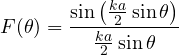
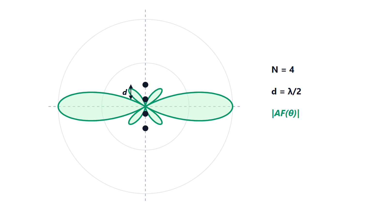
the sinc function, transform of a rectangle. The first zero falls at  , the side lobes start at −13.3 dB (the same function as the uniform array and the rectangular window), and the half-power width is about
 .
The maximum directivity of an aperture of physical area  is obtained with uniform illumination and equals
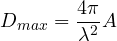
consistent with the relation between effective area and gain (lesson on parameters): a lossless uniform aperture has an effective area equal to its physical area. Doubling the diameter quadruples the gain, and so does doubling the frequency.
Aperture efficiency
Real antennas have  , with an aperture efficiency
 typically between 0.5 and 0.75. There are two main causes, in conflict with each other:
- taper: the feed sends more power to the centre than to the edges, and a non-uniform aperture has less directivity (but lower side lobes, like windows);
- spillover: the power the feed sends beyond the edge of the reflector is lost, and in reception it picks up the hot noise of the ground.
Illuminating the edges about 10 dB below the centre gives the best compromise, with efficiency around 75-80 %; to this are added losses from blockage (the feed and its supports in front of the reflector) and surface imperfections.
Horns
A horn is a waveguide that gradually flares towards the aperture: it matches the waveguide impedance to that of free space and produces an aperture a few wavelengths across, with gains of 10-25 dBi and a very wide bandwidth. Pyramidal horns are used as standard gain antennas for gain measurements, because their gain can be computed accurately from their dimensions, and as reflector feeds.
The parabolic reflector
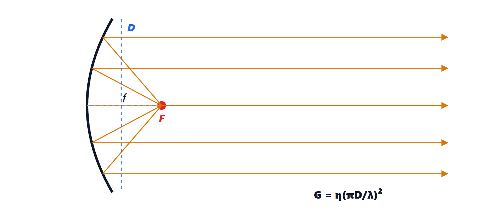
Theorem. In a paraboloid with focus  , all rays leaving the focus are reflected parallel to the axis, and the path length from the focus to a plane perpendicular to the axis is the same for all rays.
Proof. By definition, the parabola is the locus of points  equidistant from the focus and from a line, the directrix, perpendicular to the axis behind the vertex:
 , with
 the projection of onto the directrix. Consider a plane
 perpendicular to the axis in front of the parabola, at distance
 from the directrix. A ray going from to and then parallel to the axis up to travels
 , the same for every point . That the reflection takes place exactly parallel to the axis follows from the property of the tangent to the parabola, which bisects the angle between
 and the parallel to the axis (it is proved with the same equal-distance argument). ∎
Every ray reaches the aperture with the same phase: the reflector turns the feed’s spherical wave into a plane wave as wide as the diameter  . The gain is

Example. A 60 cm dish for satellite television at 11.7 GHz ( cm) with efficiency 0.65:
 , times 0.65 gives about 3500, i.e. 35.5 dBi, with a beam about 3° wide. That is why it must be pointed carefully, and why a larger dish sees weaker satellites.
In home antennas the feed is moved to the side (offset), so it does not shadow the aperture. Large radio telescopes and earth stations use dual-reflector systems (Cassegrain, Gregorian), with a second mirror sending the wave back towards a feed located behind the main reflector, where it is more convenient to place cooled receivers.