Propagation: the two-ray model, Fresnel zones, atmosphere and rain
The Friis formula, the two-ray model and the fourth-power law proved, Fresnel zones with proof and example, Earth curvature, the ionosphere, rain and gases, empirical urban models.
Between two antennas the wave rarely travels as in empty space: there is the ground reflecting it, obstacles blocking or diffracting it, the atmosphere bending it, rain absorbing it. In this lesson we start from the Friis formula and look at the two-ray model with the proof of the fourth-power law, Fresnel zones with the proof of their radius, the curvature of the Earth, ionospheric and tropospheric propagation, rain and gas attenuation, and the empirical models used for cellular networks.
Free space
In free space the Friis formula holds (Electromagnetic Fields lesson on antennas):
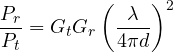
Received power falls as  : 6 dB less for every doubling of distance, 20 dB per decade.
The two-ray model
Over flat ground, the receiver gets the direct ray and the one reflected by the ground. At grazing incidence the ground reflection coefficient is about  (Electromagnetic Fields lesson on reflection).
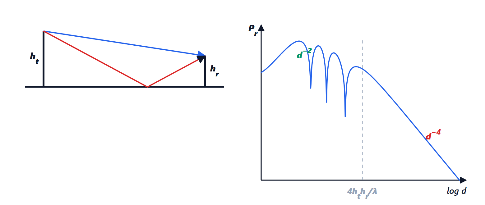
Theorem. For distances  , the path difference between the two rays is
 , and for

Proof. The direct ray travels  , the reflected one, by the image method,
 . With
 , the difference is
 . With reflection and roughly equal amplitudes, the total field is the direct one multiplied by
 . When
 , i.e. far away, the factor is about
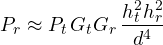
 . In power:
 . ∎
Beyond the breakpoint distance  power falls by 40 dB per decade instead of 20, and no longer depends on frequency; before it, the two rays interfere and the power oscillates. Raising the antennas helps a lot: doubling the height of either gives 6 dB.
Fresnel zones
A line-of-sight link needs more than a clear straight line between the antennas: the wave occupies a volume around it.
Theorem. The radius of the  -th Fresnel zone, at a point at distances
 and
 from the two antennas (
 ), is
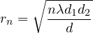
Proof. Zone is the locus of points for which the path through them exceeds the direct one by  . For a point at distance
 from the line joining the antennas, the path is
 . Requiring the excess to be :
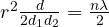 , which gives the formula. ∎
If the first zone is clear for at least 60 % of its radius, the attenuation is practically that of free space. Example. A 10 km microwave link at 6 GHz ( cm) has, at mid-path,
 m: the antennas must be raised so that at mid-path there are at least 7 m of clearance above trees and buildings. An obstacle intruding into the zone causes diffraction and extra attenuation, computed with knife-edge models.
The curvature of the Earth and the atmosphere
On long links the curvature of the Earth also matters. The refractive index of air decreases with altitude, and waves bend slightly downwards: this is accounted for by using in calculations a fictitious Earth radius equal to  of the true one, and the radio horizon turns out farther than the optical one, about
 km with
 in metres. Under particular conditions (temperature inversions over the sea) ducts form that carry VHF and UHF signals hundreds of kilometres.
Below 30 MHz the ionosphere, the layers of ionised gas between 60 and 400 km altitude, reflects short waves back to Earth: with one or more hops the antipodes can be reached, but conditions change with the time of day, the season and the solar cycle. Above a few gigahertz the ionosphere is transparent.
Rain and gases
Above 10 GHz raindrops, of size comparable to the wavelength, absorb and scatter energy: at 20 GHz a 50 mm/h storm attenuates by several decibels per kilometre. Ka-band satellite links and millimetre-wave relays are designed with a rain margin based on local statistics. Atmospheric gases have absorption lines: water vapour at 22 GHz and oxygen around 60 GHz, where attenuation exceeds 10 dB/km. The latter band is used precisely for short links that must not interfere at a distance.
Empirical models
In urban environments the rays are very many (Electrical Communications lesson on the multipath channel). To dimension networks, empirical models of the form

are used, with an exponent from 2 (free space) to 4 or more (dense cities, indoors), derived from measurement campaigns, and a random variable  representing shadowing by buildings, with a standard deviation of 6-10 dB. The Okumura-Hata models and those of the ITU and 3GPP are built in this way.