Radiation: retarded potentials, the Hertzian dipole and radiation resistance
Retarded potentials, fields of the Hertzian dipole, near and far field, radiated power and radiation resistance with proof, directivity and the half-wave dipole.
A stationary charge produces an electric field, a steady current a magnetic field; but only accelerated charges, such as the time-varying currents in an antenna, produce fields that detach from the source and carry energy to infinity. In this lesson we see how radiated fields are computed with retarded potentials, and we derive the field of the elementary dipole, the radiated power and the radiation resistance.
Retarded potentials
Rather than solving Maxwell’s equations with sources directly, it is convenient to introduce the vector potential  , with
 . In sinusoidal steady state and with a suitable choice (the Lorenz condition), satisfies the Helmholtz equation with a source,
 , whose solution is

It is the same formula as in magnetostatics with one extra factor,  : the contribution of each piece of current arrives late by
 , the time the field takes to cover the distance. From one obtains
 and, away from the sources,
 from the Ampère-Maxwell law.
The elementary dipole
The simplest case: a piece of wire of length  along the
 axis, carrying a uniform current
 (the Hertzian dipole). Far from the dipole, at distances much larger than the wavelength (the far field), the result is

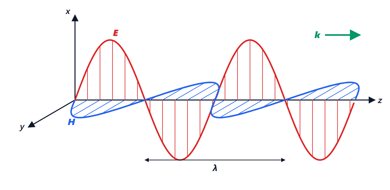
Far from the source the field is locally a plane wave: and  are perpendicular to each other and to the radial direction, with ratio
 , and decrease as
 . Close to the dipole there are also terms in
 and
 , which store energy without radiating it (the near field); the transition between the two regions happens at a distance of the order of
 for small antennas,
 for antennas of size
 .
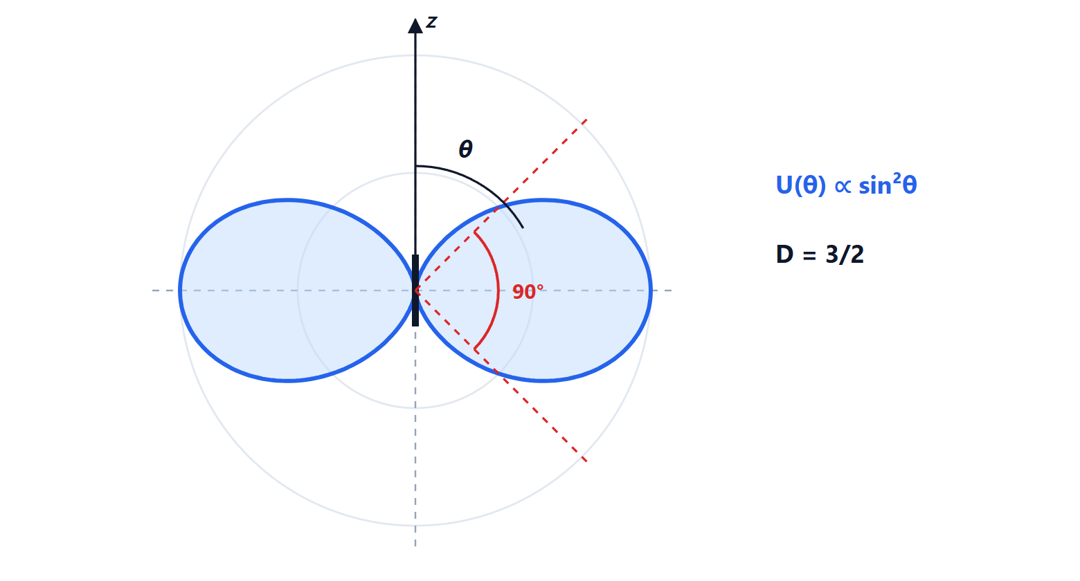
The factor  says that the dipole does not radiate along its axis and radiates most in the perpendicular plane: this is why the vertical antennas of cordless phones and radios radiate well horizontally, towards other antennas, and little towards the sky.
Radiated power and radiation resistance
Theorem. The elementary dipole radiates the average power

Proof. The average far-field Poynting vector is  . The total power is obtained by integrating over a sphere of radius
 , with
 :

where  with
 . With
 Ω and
 we get
 . ∎
The radiation resistance  is the resistance that, carrying the same current, would dissipate the radiated power: to the source, energy leaving as waves is indistinguishable from energy dissipated in a resistor.
Example. With  ,
 Ω. With
 just 0.08 Ω: an antenna much shorter than the wavelength has a tiny radiation resistance, comparable with that of the conductors, and most of the power is lost as heat. This is the problem of long-wave radio antennas and RFID tags.
Directivity of the dipole
The radiation intensity  is the power per unit solid angle. The directivity compares the maximum with the average over all directions:

that is 1.76 dBi: in its best direction the dipole radiates one and a half times more than an ideal source radiating equally in all directions (isotropic).
The half-wave dipole
The most common real antenna is the half-wave dipole: two arms each  long, fed at the centre. The current is not uniform but sinusoidal, largest at the centre and zero at the ends; repeating the calculation gives a radiation resistance of about 73 Ω, which matches 50 or 75 Ω cables well, and a directivity of 1.64 (2.15 dBi). The vertical whip antenna over a metal ground plane (quarter-wave monopole), used on cars and portable radios, is half a dipole: by the image principle it behaves like the full dipole, with half the resistance, about 36 Ω.