Antenna parameters: directivity, gain, effective area and polarisation
Radiation intensity and pattern, directivity and beam solid angle with proof, gain and efficiency, EIRP, effective area and reciprocity, polarisation loss, impedance and bandwidth.
An antenna turns a wave guided in a cable into a wave in space, and vice versa. To choose or design one it must be described with a few numbers: where it radiates, how much it concentrates power, how much it loses, how well it is matched to the cable, with what polarisation. The Electromagnetic Fields course introduced the elementary dipole, gain and the Friis formula. In this lesson we define an antenna’s parameters precisely, prove the formula linking directivity to beamwidth, and look at efficiency, effective area, polarisation, impedance and reciprocity.
The radiation pattern and directivity
Far from the antenna the field is a spherical wave, and power density falls as  . So the radiation intensity
 is used, in watts per steradian, which does not depend on distance. The radiation pattern is
 normalised to its maximum, plotted as a function of direction, often in decibels.
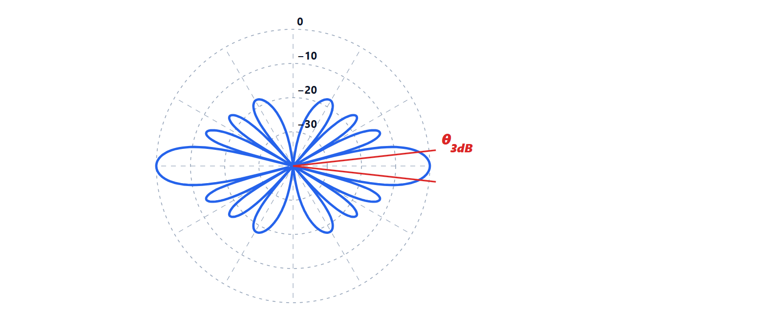
The total radiated power is the integral of the intensity over all directions,  . Directivity compares the intensity in one direction with that of an ideal antenna radiating uniformly in all directions (isotropic):

Its maximum is simply called the directivity  , and it is expressed in dBi (decibels relative to isotropic).
Theorem. If almost all the power is concentrated in a beam with half-power widths  and
 (in radians) in the two principal planes,
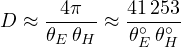
Proof. Define the beam solid angle  : the solid angle in which all the power would have to lie if the intensity were everywhere equal to its maximum. Then
 . If the beam is narrow and the side lobes are small,
 is about the area of the beam, i.e. the product of the two widths,
 . In square degrees the whole sphere is
 . ∎
Example. An antenna with a  beam has
 , i.e. about 26 dBi. The formula overestimates slightly, because it neglects the power in the side lobes; practical estimates use 30 000-35 000 in the numerator.
Gain and efficiency
Not all the power delivered to the antenna is radiated: part is lost in conductors and dielectrics. The radiation efficiency is  , and the gain is
 . If the antenna is not matched to the cable, part of the power is also reflected back, by a factor
 (Electromagnetic Fields lesson on matching); the realised gain includes this loss too. The product of transmitted power and gain is the equivalent isotropically radiated power (EIRP), the value on which regulations set emission limits.
Effective area and reciprocity
In reception an antenna behaves like a surface collecting the power of the incident wave:  , where
 is the effective area. The link with gain is

and it is this which, combined with the definition of gain, gives the Friis formula. It holds by reciprocity: an antenna made of linear materials has the same pattern, gain and impedance in transmission and in reception. That is why an antenna can be measured in reception and used to transmit.
Polarisation
An antenna’s polarisation is that of the wave it radiates: linear (vertical, horizontal), circular (right or left) or elliptical. In reception alignment matters: the polarisation loss factor is  , the square of the scalar product of the polarisation unit vectors. Two linear antennas crossed at 90° do not talk to each other (in theory infinite loss, in practice 20-30 dB); a linear antenna receiving a circular wave always loses half the power, 3 dB, whatever its orientation. That is why navigation satellites use circular polarisation: the receiver need not know how it is oriented.
Impedance and bandwidth
At its terminals an antenna is a load of impedance  : the radiation resistance
 represents the radiated power,
 the power lost,
 the energy stored in the near field. Efficiency is
 . An antenna is resonant when
 , and its bandwidth is the frequency range over which matching remains acceptable, typically with a standing-wave ratio below 2 (reflection loss below 0.5 dB). Antennas that are small compared with the wavelength have small radiation resistance and large reactance: they are hard to match, inefficient and narrowband. It is the physical limit that makes antennas for wearable devices difficult.