Solved exercises on anisotropic media: ferrite, Faraday rotator, circulator, wave plates, ionosphere, Hall effect
Eight exercises with solutions and graphs: Polder tensor, resonance field and YIG filters, plasma frequency and secant law, Faraday rotator and isolator, circulator in radar, wave plates with Jones calculus, Faraday rotation in satellite links, Hall sensors.
Exercises on anisotropic media of the kind found in Electromagnetic Fields and Microwaves exams, in three levels: basic, with direct calculation of the tensors; intermediate, with the devices (Faraday rotator, circulator, wave plates); exam, with the ionosphere and the Hall effect. Constants:  GHz/T for the electron, YIG ferrite with
 T and
 . The result is given immediately; the full solution, with the graph, opens with a click. The proofs are in the linked lesson.
Basic level
Exercise 1. The Polder tensor
A YIG ferrite is magnetised by a field  T. Compute, at 10 GHz, the resonance frequency, the elements
 and
 of the tensor and the permeabilities of the two circular waves.
Result:  GHz;
 ,
 ;
 ,
 .
Solution
1.  GHz;
 GHz. Frequencies can be used in the formulas instead of angular frequencies, because only ratios appear.
2.  .
3.  . The negative sign only says that we are above resonance (
 ).
4.  :
 ,
 . Check:
 . The two circular waves see permeabilities differing by a factor 3.4.
Exercise 2. The field for resonance
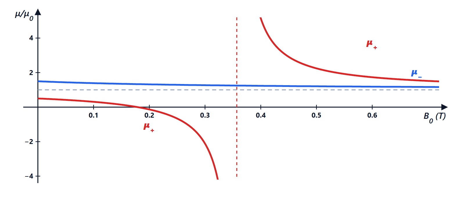
What field is needed to bring a ferrite to resonance at 10 GHz? And at 3 GHz? A YIG sphere filter is tuned by varying the current of an electromagnet: by how much must the field change to move it from 2 to 18 GHz?
Result: 0.357 T at 10 GHz, 0.107 T at 3 GHz; from 0.071 to 0.643 T.
Solution
1. Resonance is at  , so
 :
 T and
 T.
2. For a 2 to 18 GHz filter: from  T to
 T. Frequency is proportional to the field, hence to the electromagnet current: the filter tunes linearly over almost three octaves. This is the principle of the YIG oscillators and filters in spectrum analysers.
3. Note that the resonance of a free electron (cyclotron) has the same constant:  GHz/T. This is no coincidence: in both cases the charge-to-mass ratio of the electron governs the rotation.
Exercise 3. The plasma frequency
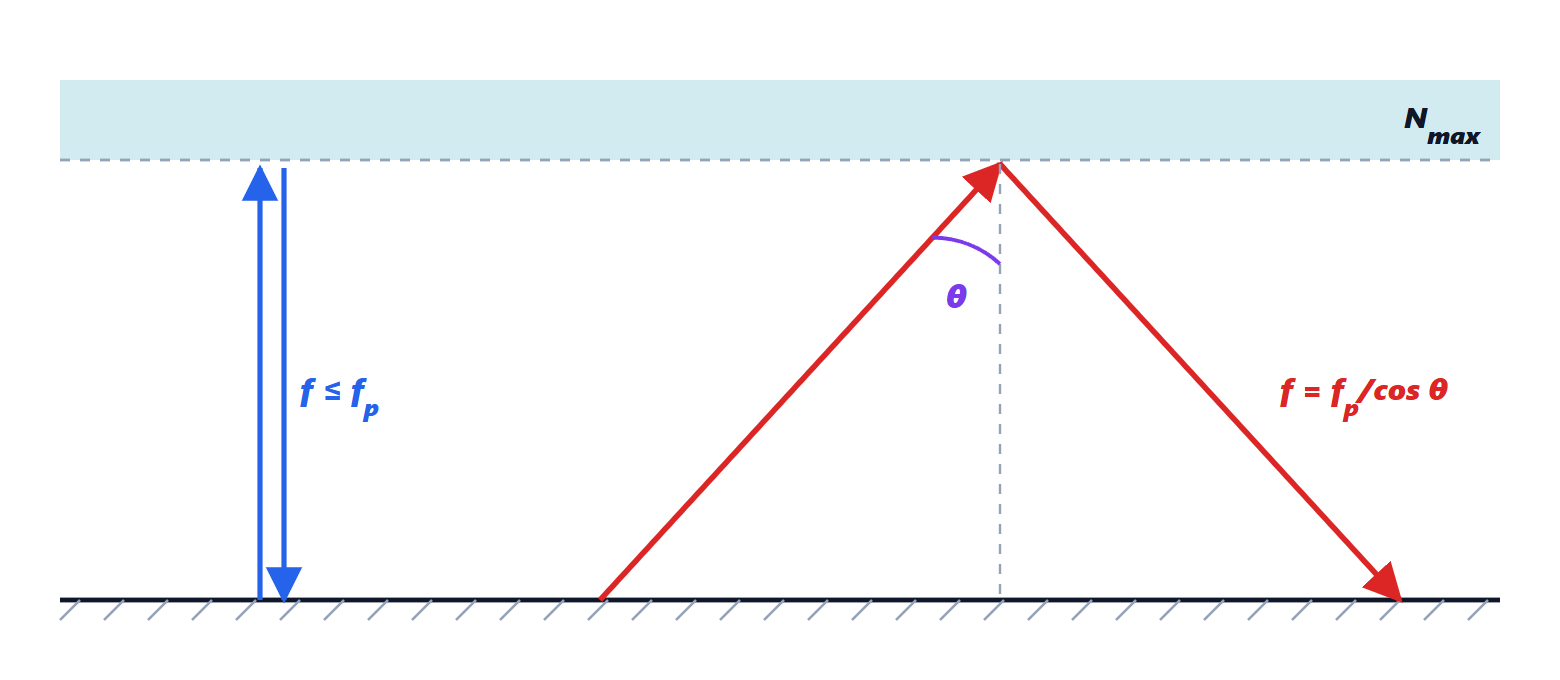
The densest region of the ionosphere has  electrons/m³. Compute the plasma frequency. Up to what frequency does a wave sent vertically come back to the ground? And with an incidence of 75° from the vertical?
Result:  MHz; with 75° oblique incidence up to 34.7 MHz.
Solution
1.  MHz. A handy formula:
 Hz.
2. At vertical incidence the wave is reflected where  , i.e. where the local plasma frequency equals its own: it comes back only if
 MHz. This is what an ionosonde measures.
3. At oblique incidence only the vertical component of the wave vector matters (Snell’s law in the stratified ionosphere conserves the horizontal one): the wave comes back if  . With
 °:
 MHz. This is the secant law: grazing short waves reach distances of thousands of kilometres even at 20-30 MHz.
Intermediate level
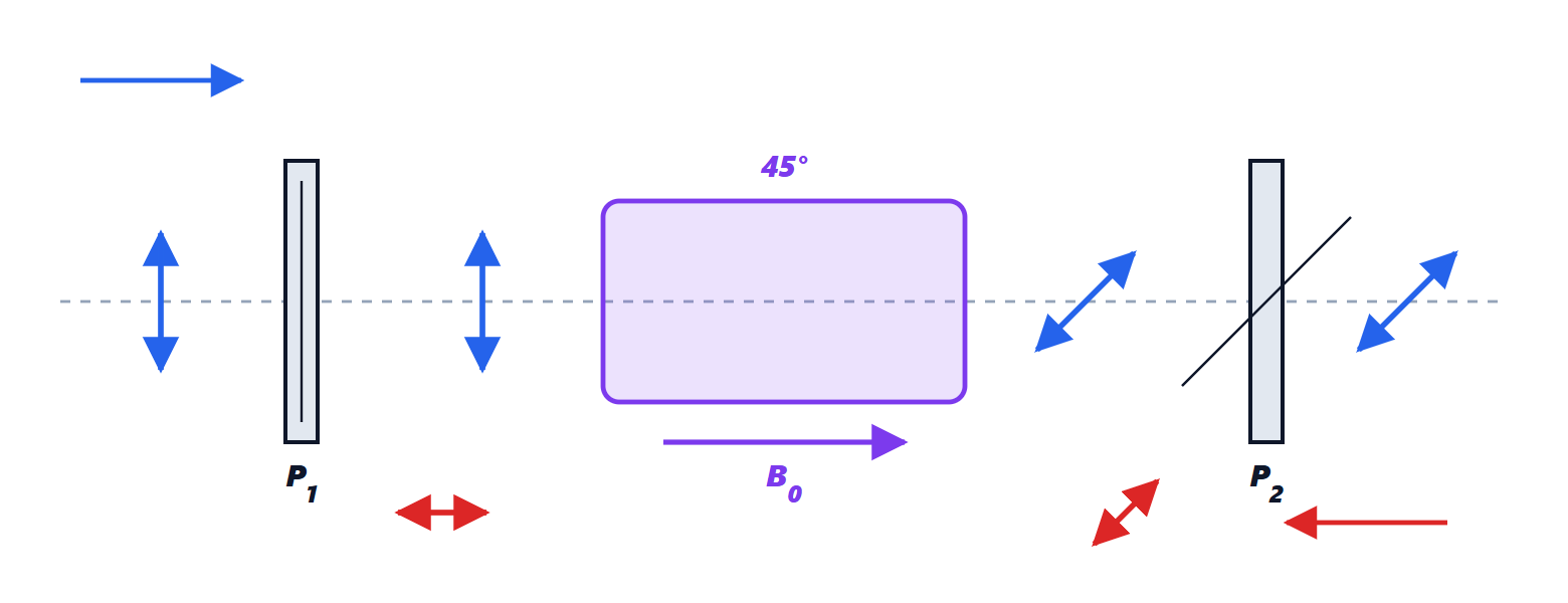
Exercise 4. The Faraday rotator
With the ferrite of exercise 1 (), at 10 GHz, compute the phase constants of the two circular waves, the rotation per millimetre and the length of a 45° rotator (unbounded medium). What happens to the reflected wave?
Result:  rad/m,
 rad/m; 12.8° per millimetre; 3.5 mm; the reflected wave rotates by another 45°, 90° in total.
Solution
1.  , with
 rad/m:
 rad/m,
 rad/m.
2. Rotation:  rad/m, i.e. 12.8° per millimetre.
3. For 45° (0.785 rad):  mm. In real devices the ferrite only partly fills the waveguide and the rotation is smaller: waveguide rotators are a few centimetres long.
4. The reflected wave comes back through the same ferrite: the sense of rotation is fixed by the field  , not by the direction of propagation, so it rotates by another 45° in the same sense. 90° in total: it arrives perpendicular to the input polariser and is absorbed. This is the isolator.
Exercise 5. The circulator in radar
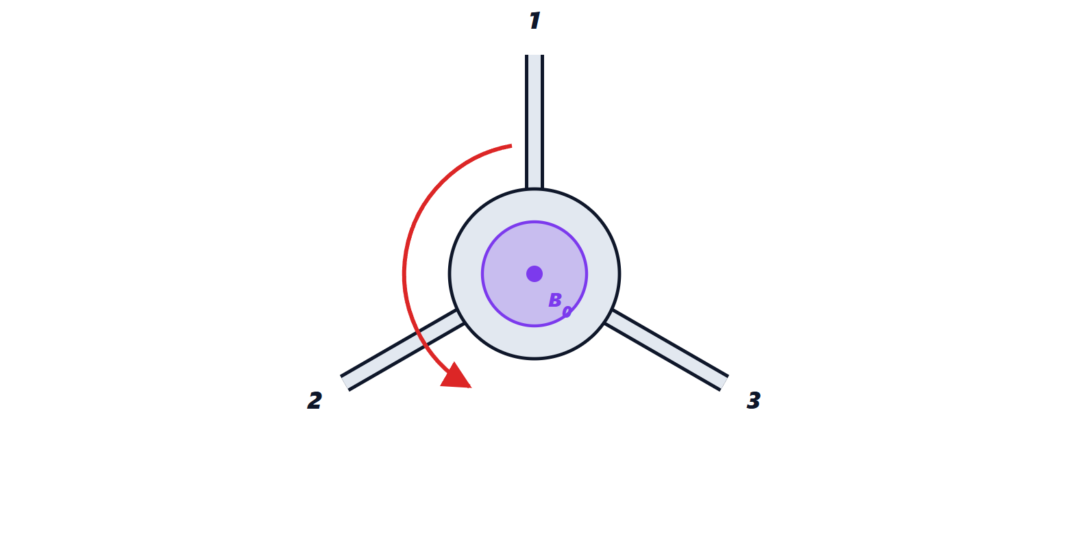
A radar uses a single circulator to connect transmitter (port 1), antenna (port 2) and receiver (port 3). The transmitter emits 1 kW pulses; the real circulator has 20 dB of isolation between port 1 and port 3. How much power reaches the receiver directly from the transmitter? Why can the circulator not be made with passive reciprocal components only?
Result: 10 W, much more than a receiver can withstand: a limiter is needed. A lossless, matched and reciprocal three-port network does not exist.
Solution
1. 20 dB means a factor 100:  W (+40 dBm). A low-noise amplifier usually withstands a few milliwatts: a PIN-diode limiter or a switch that closes during the pulse is placed in front of the receiver. Moreover the antenna is not perfectly matched: a VSWR of 1.5 reflects 4 % of the power, another 40 W that the circulator sends right to the receiver.
2. The ideal circulator has 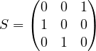 : it is unitary (orthonormal columns, hence lossless) but not symmetric (
 ,
 ). As proved in the lesson, if it were symmetric the orthogonality of the columns and their unit norm would be incompatible. A non-reciprocal medium is needed: magnetised ferrite.
Exercise 6. Wave plates
Compute the thickness of a zero-order quarter-wave plate in quartz ( ,
 ) and in calcite (
 ,
 ) for
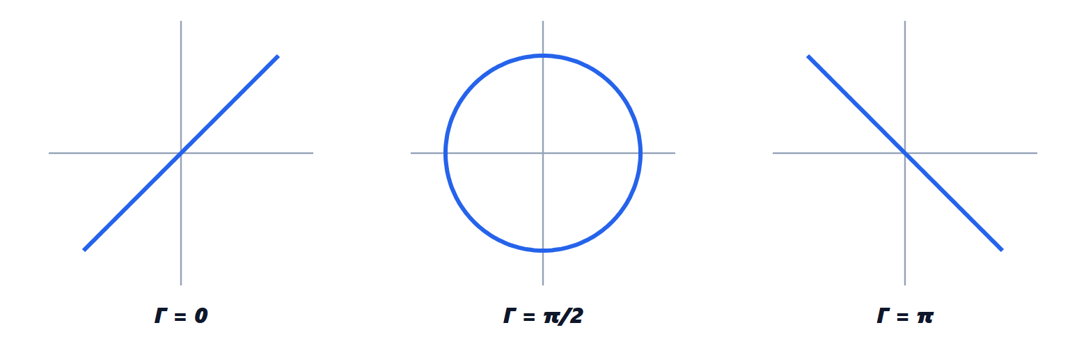
 nm. Then, with Jones calculus, check that a half-wave plate with its axis at 22.5° rotates horizontally polarised light by 45°, and that a quarter-wave plate at 45° makes it circular.
Result: quartz 17.4 μm, calcite 0.93 μm (too thin to machine); outputs  and
 , i.e.
 .
Solution
1.  : quartz
 μm; calcite
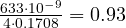 μm. This is why plates are made of quartz or weakly birefringent polymers, or “multiple-order” (phase difference
 ), thicker but more sensitive to wavelength and temperature.
2. Half wave ( ) at
 °:
 , a reflection about the axis. On
 it gives
 : linear at 45°, i.e. rotated by
 .
3. Quarter wave ( ) at 45°: the matrix is
 ; on it gives , with
 : components equal in magnitude and 90° out of phase, circular polarisation.
Exam level
Exercise 7. Faraday rotation in satellite links
A ground station receives with a linearly polarised antenna the signal of a satellite, also linear. The path crosses the ionosphere with  m⁻² and field
 μT parallel to the path. Compute the Faraday rotation and the polarisation mismatch loss at 150 MHz, 1.5 GHz and 12 GHz. What solution is adopted?
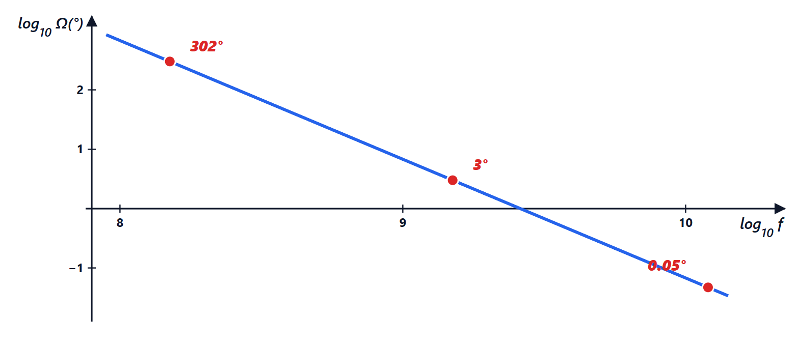
Result: 301°, 3.0° and 0.05°; losses 5.7 dB, 0.012 dB and negligible; at VHF and L band circular polarisation is used.
Solution
1.  rad: at 150 MHz 5.26 rad = 301° (the exact calculation with the complete indices gives 302°), at 1.5 GHz 0.0526 rad = 3.0°, at 12 GHz 0.05°.
2. The signal arrives rotated by  with respect to the antenna: the received power is reduced by
 . At 150 MHz
 , i.e. 5.7 dB. But TEC varies by a factor of 10 between day and night, so the rotation changes by hundreds of degrees and sooner or later the wave arrives perpendicular to the antenna: total fading. At 1.5 GHz the loss is 0.012 dB, at 12 GHz zero.
3. A circular wave is an eigenvector of the medium: Faraday rotation only changes its phase, not its polarisation. This is why GPS, VHF weather satellites and telemetry use circular polarisation; satellite TV at 12 GHz can use linear (and does, to double the channels with two orthogonal polarisations).
Exercise 8. Hall sensors
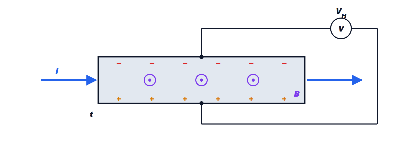
A 0.1 mm thick bar, in a 1 T field, carries a current. Compute the Hall voltage for a copper bar ( m⁻³) with 1 A and for a semiconductor with
 m⁻³ with 1 mA. What does the sign of
 measure? Why does the resistance of the bar not change with the field, in the Drude model?
Result: copper 0.73 μV; semiconductor 6.2 mV; the sign gives the sign of the carriers;  whatever
 .
Solution
1.  . Copper:
 μV: too little for a practical sensor. Semiconductor:
 mV, with a current a thousand times smaller. The voltage grows when carriers are few, because for the same current they must move faster and the Lorentz force
 is larger.
2. The sign of the voltage depends on the sign of the carriers: this is how it was discovered that in some semiconductors (p-type) current is carried by positive charges, the holes.
3. Inverting the conductivity tensor gives : in steady state the Hall field exactly balances the Lorentz force, and the electrons go straight as without a field. The magnetoresistance measured in real materials arises from the velocity distribution and from the presence of several types of carriers, which the Drude model ignores.