Solved exercises on current, DC circuits and the RC circuit
Thirteen exercises with solutions: resistivity, drift velocity, series and parallel, maximum power transfer, Drude model, Kirchhoff's laws, Wheatstone bridge, RC charge and discharge, light bulb, coaxial cable, Hall effect, Thévenin.
Exercises on electric current, resistance, DC circuits and the RC circuit of the kind set in Physics 2 courses, in three levels: basic, for resistivity, drift velocity and resistor combinations; intermediate, with the microscopic model, Kirchhoff’s laws, the Wheatstone bridge and RC transients; exam, with complete problems as in written exams. The result is given straight away; the full solution opens with a click. The proofs are in the lesson and the in-depth study linked at the top.
Constants:  C,
 kg; copper:
 Ω·m,
 m
 .
Basic level
Exercise 1. The resistance of a wire
Compute the resistance of a copper wire 50 m long with a diameter of 1.0 mm. What diameter should an aluminium wire ( Ω·m) of the same length have to give the same resistance?
Result: 1.08 Ω; 1.28 mm.
Solution
Cross-section:  m². Resistance:
 Ω.
For the same  with the same length we need
 , and the diameter goes as the square root:
 mm. Despite the larger cross-section, the aluminium wire weighs about half as much (density 2.7 against 8.9 g/cm³): this is why overhead lines are made of aluminium.
Exercise 2. How slow the drift is
A current of 10 A flows in a 2.5 mm² copper cable. Find the drift velocity of the electrons and the time they take to travel 1 m.
Result:  m/s; about 57 minutes.
Solution
Current density:  A/m². Drift velocity:
 m/s.
Time for 1 m:  s, almost an hour. The bulb lights up immediately because the field propagates, not the electrons.
Exercise 3. Series and parallel
In the circuit of the figure  V,
 Ω,
 Ω,
 Ω. Find the equivalent resistance and the currents
 ,
 ,
 .
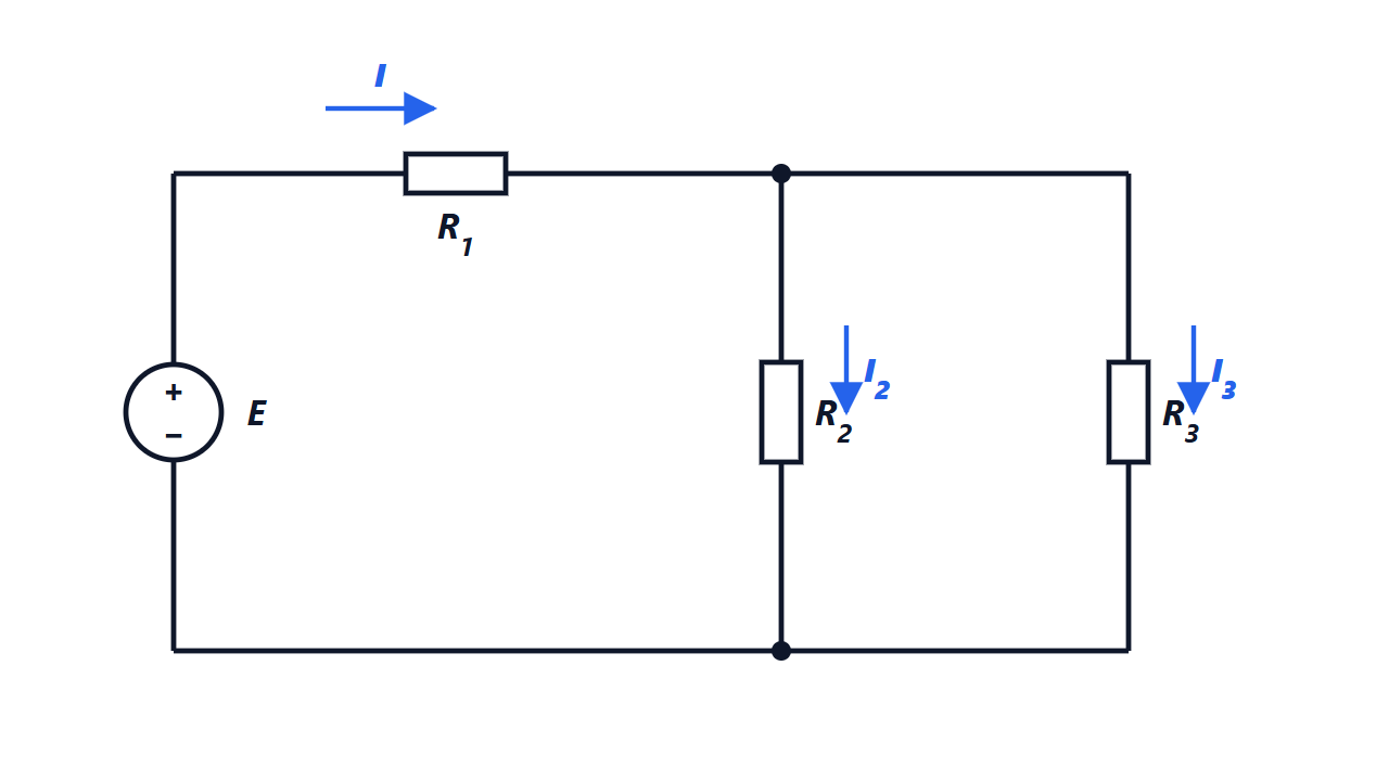
Result:  Ω;
 A,
 A,
 A.
Solution
Parallel: 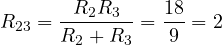 Ω. In series with
 : Ω.
Total current  A. Voltage across the parallel pair:
 V. So
 A and
 A. Check:
 .
Current divider rule: in a parallel combination the current splits in inverse proportion to the resistances.
Exercise 4. Real source and maximum power transfer
A battery has an electromotive force of 12 V and internal resistance 0.5 Ω, and is connected to a 5.5 Ω load. Find the current, the terminal voltage and the power in the load. For which load resistance would the power be maximum, and what would the efficiency be?
Result: 2 A; 11 V; 22 W; maximum for  Ω, 72 W, efficiency 50 %.
Solution
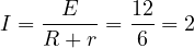 A. Terminal voltage
 V. Power in the load
 W.
Power as a function of :  . Differentiating,
 , which vanishes for
 . Then
 W.
Efficiency  : with half of the power is lost in the source. This is why maximum transfer is sought for signals (antennas, amplifiers), never in power distribution, where one wants
 .

Intermediate level
Exercise 5. The Drude model for silver
Silver has resistivity  Ω·m and
 free electrons per m³. Compute the mean time between collisions and the drift velocity in a 1 mm² wire carrying 1 A.
Result:  s;
 m/s.
Solution
From the Drude model (in-depth study)  , so

Drift velocity:  m/s, a little more than copper because silver has fewer free electrons per unit volume.
Silver conducts better than copper despite having fewer carriers: the time between collisions is longer ( against
 s).
Exercise 6. Kirchhoff’s laws with two sources
In the circuit of the figure  V,
 V,
 Ω,
 Ω,
 Ω. Find the three currents. Does the source
 deliver or absorb power?

Result:  A,
 A,
 A; absorbs 1.56 W (it is being charged).
Solution
Use nodal analysis: taking B as reference (0 V), the only unknown is the potential  . With the directions of the figure:
 ,
 ,
 .
Current law at A:  :

Multiplying by 4:  , so
 V.
Currents:  A;
 A;
 A. Check:
 .
negative means that the current in the right branch flows opposite to the arrow: it enters the positive terminal of . The source absorbs the power  W: it is a battery being charged.
Balance:  delivers
 W; the resistors dissipate
 W; plus 1.56 W absorbed by makes 18.75 W.
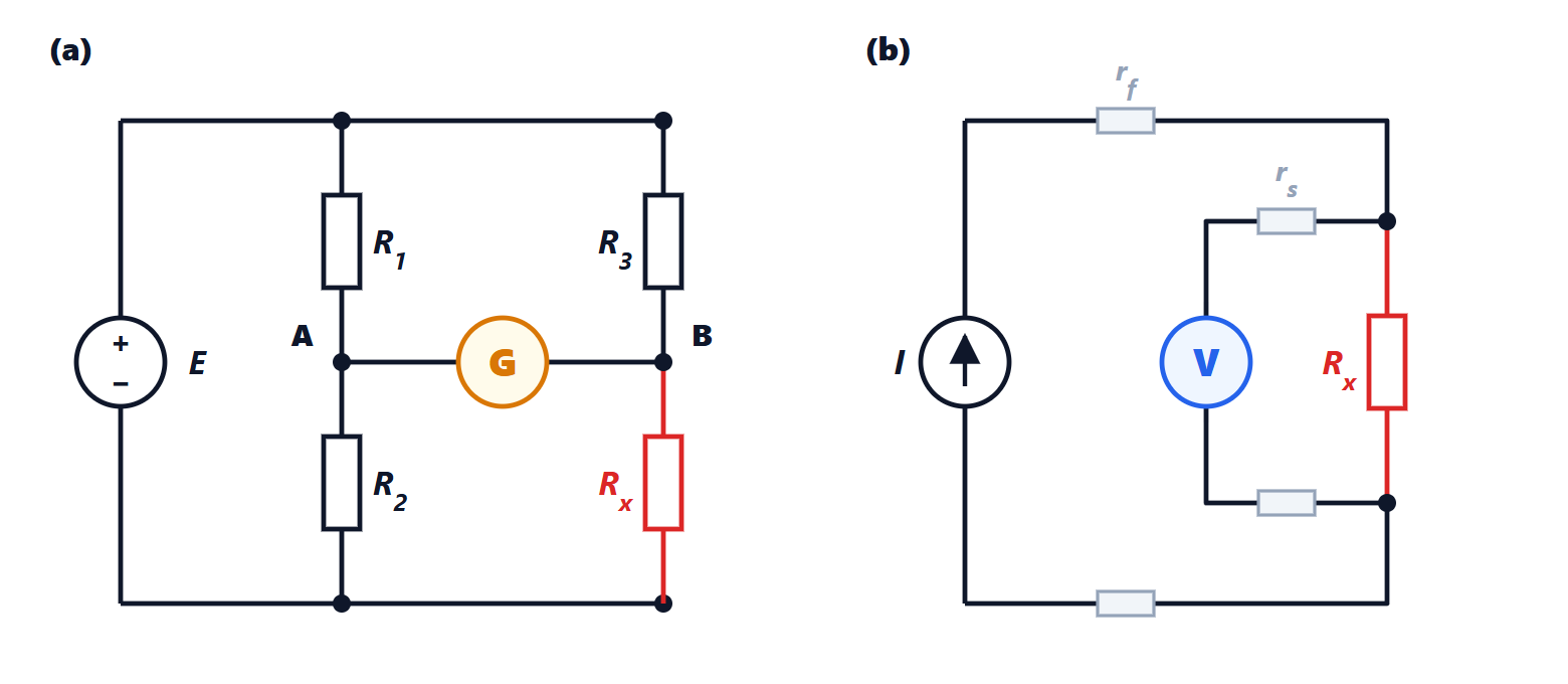
Exercise 7. The Wheatstone bridge
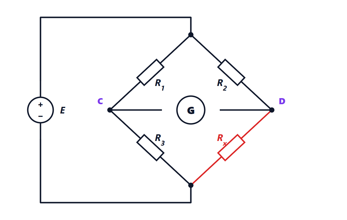
In the bridge of the figure  Ω,
 Ω,
 Ω. The galvanometer G reads zero. What is
 ? Prove the balance condition.
Result:  Ω.
Solution
If no current flows in the galvanometer, C and D are at the same potential and the two sides of the bridge are two independent dividers, fed by the same voltage  .
Left side:  (relative to the bottom vertex). Right side:
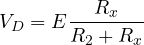 .
 gives
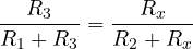 , i.e.
 , and therefore

The condition depends neither on nor on the galvanometer resistance: this is why the bridge measures resistances very accurately, and in its unbalanced version it is the circuit of strain gauges and bridge sensors.
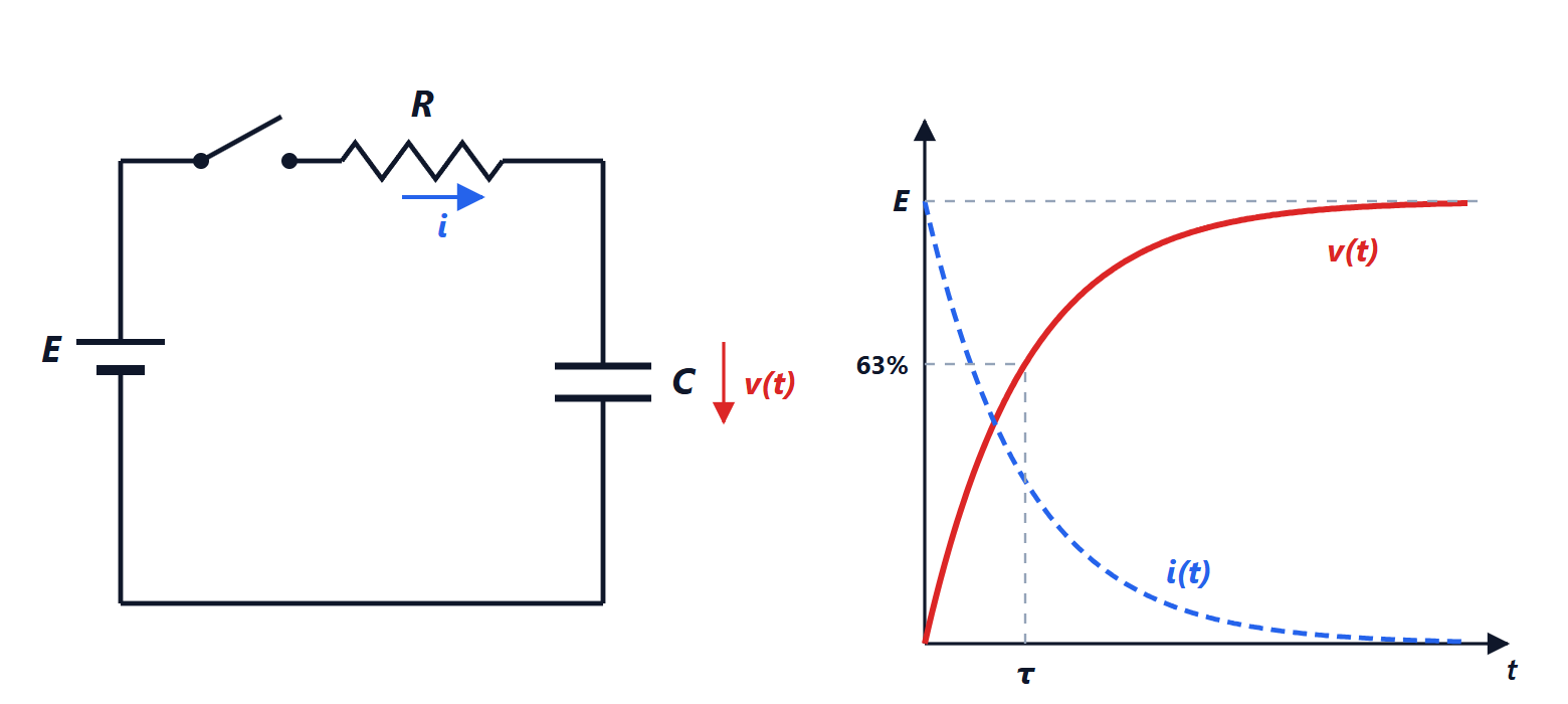
Exercise 8. Charging a capacitor
A 47 µF capacitor, initially uncharged, is charged through a 10 kΩ resistor from a 9 V battery. Find the time constant, the initial current, the time to reach 6 V and the energy stored at the end.
Result:  s; 0.90 mA; 0.52 s; 1.9 mJ.
Solution
 s. At the initial instant the capacitor is a short circuit:
 mA.
From  :
 , so
 s.
Final energy:  mJ. The battery supplied twice as much,
 mJ: the other half was dissipated in the resistor (lesson).
Exercise 9. Discharging a capacitor
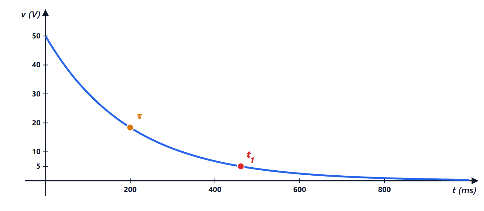
A 100 µF capacitor charged to 50 V discharges through a 2 kΩ resistor. After how long does the voltage fall to 5 V? How much energy is dissipated in total?
Result: 0.46 s; 0.125 J.
Solution
During discharge  , with
 s.
 gives
 s. Every time constant the voltage drops to
 %.
Energy: all the stored energy,  J, ends up as heat in the resistor. Check by integration:
 J.
Exam level
Exercise 10. The incandescent bulb
A tungsten-filament bulb is rated 60 W at 230 V. At room temperature (20 °C) the filament measures 70 Ω. With the temperature coefficient  K
 , estimate the operating temperature, and compare the current at switch-on with the steady-state current.
Result: about 2600 °C; at switch-on 3.3 A against 0.26 A in steady state (about 13 times).
Solution
Hot resistance:  Ω.
With the linear law  :
 , so
 K and
 °C. (The linear law is only an approximation over such a wide range, but the order of magnitude is right: tungsten melts at 3422 °C.)
Currents: in steady state  A; at switch-on, with the filament cold,
 A (rms values). The peak lasts a few milliseconds, until the filament heats up, and it is why bulbs almost always burn out at the moment they are switched on.
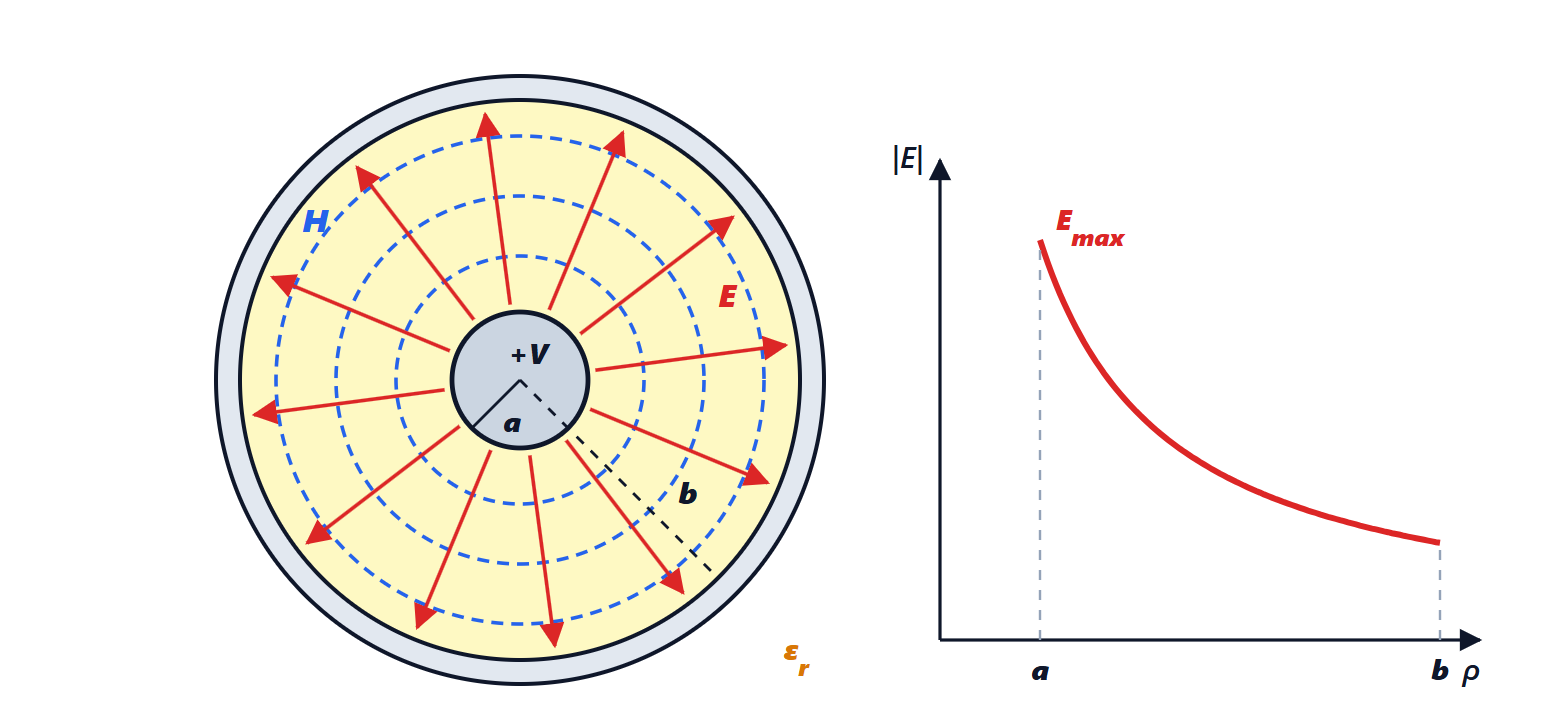
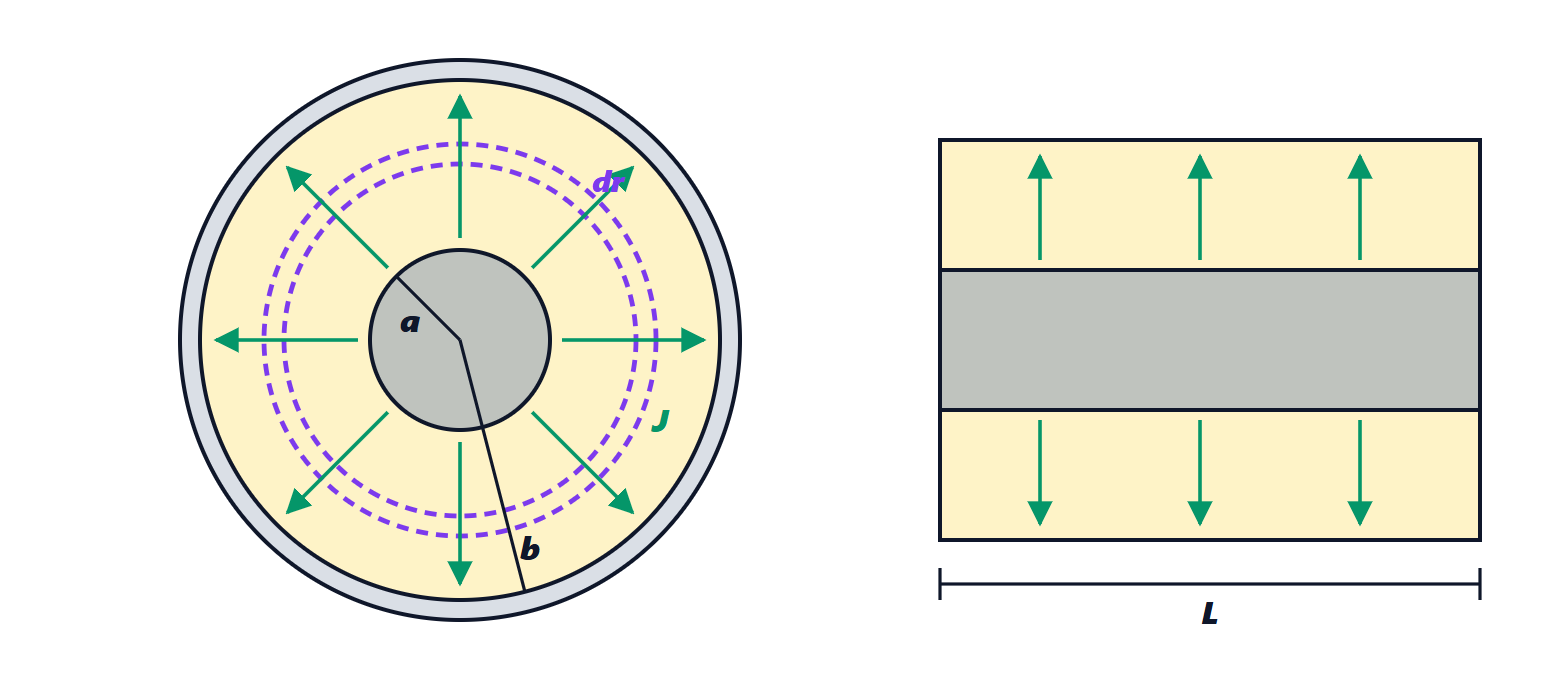
Exercise 11. The insulation of a coaxial cable
A coaxial cable 100 m long has an inner conductor of radius 0.50 mm and a braid of radius 1.75 mm, separated by polyethylene ( Ω·m,
 ). Compute the insulation resistance, the leakage current at 1 kV, and the product
 of insulation resistance and cable capacitance.
Result:  Ω; 50 nA;
 s, independent of geometry.
Solution
Radial resistance (in-depth study):  Ω. Current at 1 kV:
 nA.
Capacitance of the coaxial cable:  nF.
Product:  s.
The result  holds for any pair of electrodes immersed in a homogeneous medium, because resistance and capacitance depend on geometry in inverse ways. It is the time in which a capacitor with that dielectric discharges by itself through leakage.
Exercise 12. Measuring carrier density with the Hall effect
A semiconductor strip 0.20 mm thick carries 5.0 mA in a perpendicular magnetic field of 0.50 T. A Hall voltage of 25 mV is measured, with the sign indicating negative carriers. Find the carrier density and compare it with copper.
Result:  m, about 27 million times less than copper.
Solution
From the Hall effect formula (in-depth study)  :

Ratio to copper:  . It is precisely because
 is small that the Hall voltage is large and measurable: in copper, with the same data, it would be about 1 nV.
The sign says that the carriers are electrons: it is an n-type semiconductor.

Exercise 13. An RC circuit with Thévenin’s theorem
In the circuit of the figure V,  kΩ,
 kΩ,
 µF, and the capacitor is initially uncharged. Find the capacitor voltage as a function of time and the current delivered by the source at the beginning and at the end.

Result:  V; source current 3.0 mA at the start and 0.75 mA in steady state.
Solution
Seen from the capacitor terminals, the rest of the circuit is a divider. Thévenin: open-circuit voltage  V; resistance with the source turned off (short circuit)
 kΩ.
The equivalent circuit is a simple RC:  ms, and
 V. The capacitor does not reach 12 V but 9 V, the steady-state voltage across
 .
Source current: at the start the capacitor is a short circuit that bypasses , so  mA. In steady state the capacitor is an open circuit, and
 mA.