AC circuits: phasors, impedance and resonance
RMS value, phasors and complex numbers, impedance of resistors, capacitors and inductors, the series RLC circuit, resonance and quality factor, power and power factor.
The mains, audio signals and radio signals are sinusoidal voltages. Studying a circuit of resistors, capacitors and inductors in sinusoidal steady state with differential equations is possible but long. The phasor method, which uses the complex numbers of Analysis 1, turns derivatives into multiplications and the circuit into an Ohm’s law problem. In this lesson we cover RMS values, phasors, impedance, the series RLC circuit with resonance, and AC power.
Sinusoidal quantities and RMS value
A sinusoidal voltage is written  , with amplitude
 , angular frequency
 and phase
 . Its average is zero, so to measure its “strength” the RMS value is used: the DC voltage that would dissipate the same average power in a resistor.
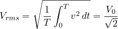
because the average of  over a period is
 . The 230 V of the European mains is an RMS value: the amplitude is
 V.
Phasors
With Euler’s formula,  . In a linear circuit every quantity oscillates at the same frequency
 , so the factor
 is common and can be left implicit. What remains is the complex number

the phasor, holding amplitude and phase. The advantage is huge: differentiating with respect to time becomes multiplying by  , because
 . The circuit’s differential equations become algebraic equations.
Impedance
For each component the ratio of the voltage phasor to the current phasor is the impedance  :
| Component | Time-domain law | Impedance | Phase of  relative to  |
|---|---|---|---|
| resistor |  |  | in phase |
| inductor |  |  | leads by 90° |
| capacitor | 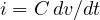 |  | lags by 90° |
With impedances, Ohm’s law  , Kirchhoff’s laws and the series and parallel rules all hold, exactly as for resistors in DC. An inductor’s impedance grows with frequency (it blocks high frequencies), a capacitor’s falls (it blocks DC): the principle of every filter.
Example. A 1 µF capacitor at 50 Hz has  kΩ; at 1 MHz only 0.16 Ω. That is why decoupling capacitors next to chips “short” high-frequency noise to ground without touching the DC supply.
The series RLC circuit
With  ,
 and
 in series, the total impedance is

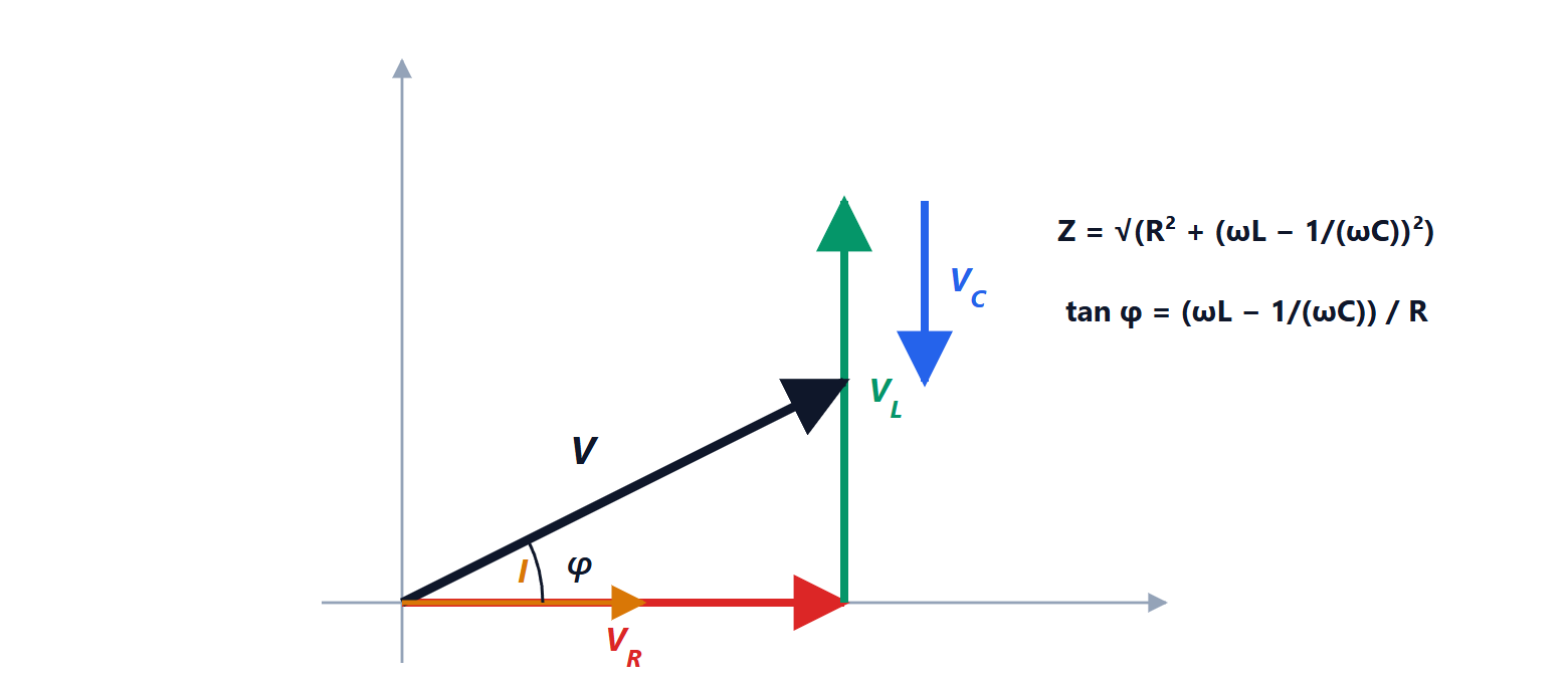
Resonance
The reactances of inductor and capacitor have opposite signs and cancel when

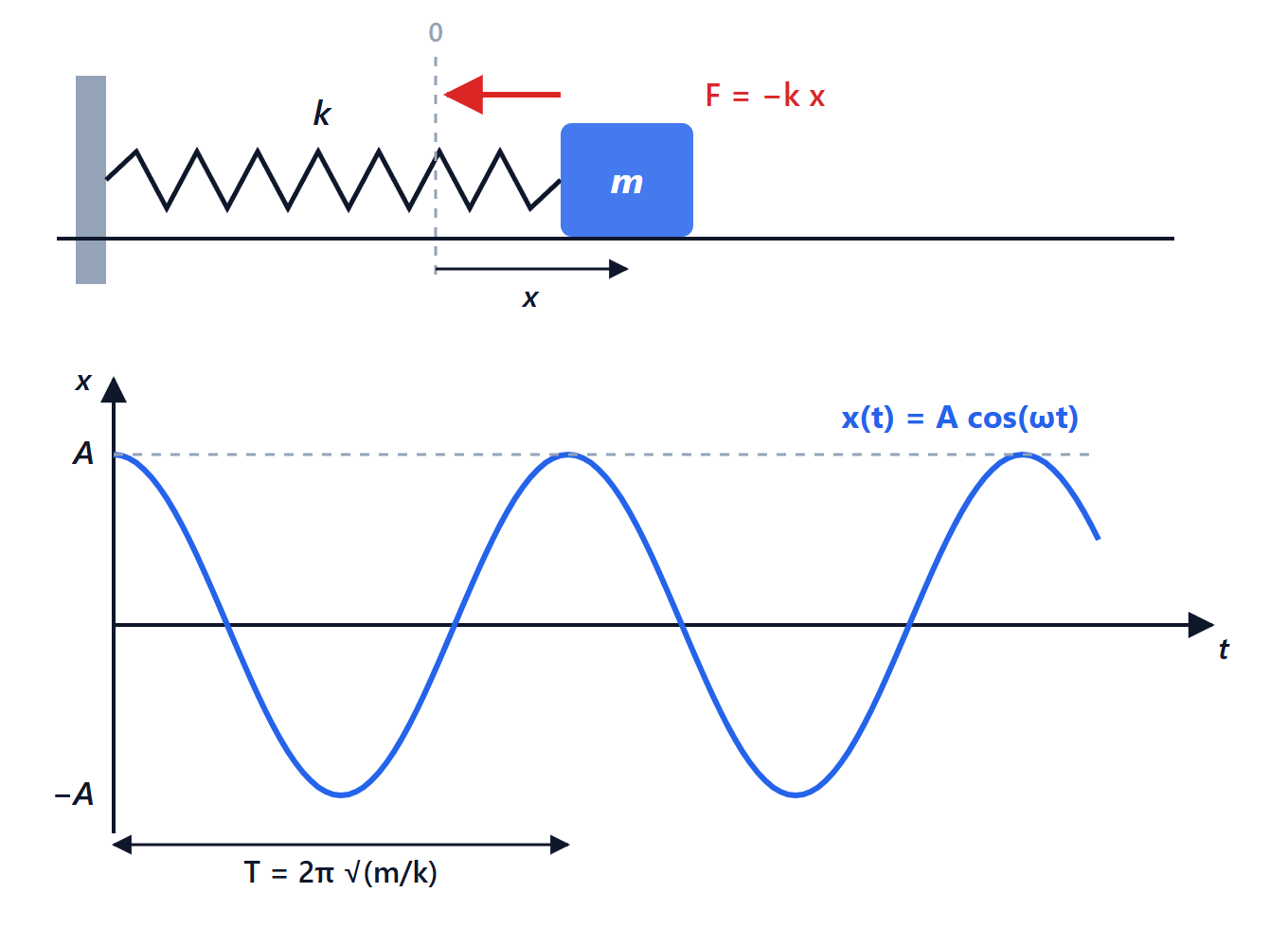
At the resonant frequency the impedance is smallest and equal to , the current is largest and in phase with the voltage. The voltages across the inductor and the capacitor can be much larger than the applied one, because they are opposite and cancel each other: their ratio to the applied voltage is the quality factor 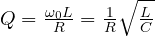 .
The bandwidth, the range of frequencies where the power is at least half the maximum, is  , that is
 . A high-
 circuit selects a narrow band: the tuning circuit of a radio. Example: with
 µH and
 pF,
 MHz; with
 Ω,
 and the bandwidth is about 32 kHz.
AC power
The instantaneous power  oscillates. Its average, the active power, is

 is the power factor. In a resistor
 and all the power is dissipated. In an ideal inductor or capacitor
 and the average power is zero: energy flows in and back out twice per period, without being consumed. The part shuttling back and forth is the reactive power,
 , measured in VAR.
A load with a low power factor, such as an uncompensated induction motor, draws more current than needed for the same active power, and needlessly heats cables and transformers. That is why large users must correct it with capacitor banks, and why power supplies above a certain rating have a power factor correction (PFC) circuit.
Power transfer
With a source of internal impedance  , the load receives the most power when
 , the complex conjugate: the reactances cancel (resonance) and the resistances are equal. It is the principle of impedance matching, essential in radio-frequency circuits, where antennas, cables and amplifiers are all matched to 50 Ω.