Resistance measurement: voltmeter-ammeter method, four-wire and Wheatstone bridge
Upstream and downstream connection with the crossover value proved, four-wire measurement, balance and sensitivity of the Wheatstone bridge with proof, AC bridges, very large resistances.
Measuring a resistance looks like the simplest thing: apply a voltage, measure the current and divide. In practice the instruments, the leads and the contacts add errors that can exceed the quantity being measured. In this lesson we look at the voltmeter-ammeter method with its two connections, four-wire measurement for small resistances, the Wheatstone bridge with the proof of balance and sensitivity, and AC bridges.
The voltmeter-ammeter method
One measures the voltage across the resistor and the current through it, and computes  . There are two ways of connecting the instruments, and neither is perfect.
Voltmeter downstream (voltmeter directly across  , ammeter before the parallel combination). The voltmeter reads the right voltage, but the ammeter also measures the current drawn by the voltmeter. The parallel combination is measured:

Voltmeter upstream (voltmeter across the series of ammeter and ). The ammeter reads the right current, but the voltmeter also measures the drop across the ammeter. The series combination is measured:

Theorem. The downstream connection is better for  , the upstream one for
 .
Proof. Compare the magnitudes of the relative errors, in the usual case  : the downstream connection is off by
 , the upstream one by
 . The first grows with , the second decreases. They are equal when
 , i.e.
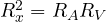 . Below this value the downstream error is the smaller, above it the upstream one is. ∎
With  Ω and
 MΩ the crossover is about 3 kΩ. The practical rule: small resistances downstream, large resistances upstream. In both cases the error is systematic and, knowing
 and
 , it can be corrected.
Small resistances: four-wire measurement
Below one ohm a new enemy appears: the resistance of leads and contacts, which can be tens of milliohms. A two-wire multimeter measures the sum of everything between its terminals.
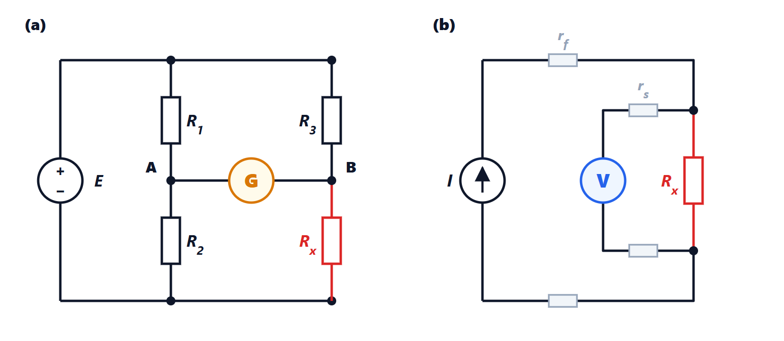
The solution is the four-wire (or Kelvin) method: two leads carry the test current, two more, connected directly across the resistor inside the first pair, read the voltage. The voltmeter has a very high resistance, so no current flows in the voltage leads and there is no drop across them: it reads exactly  . The resistances of the current leads do not matter, because the source imposes the current whatever they are.
Example. A 0.1 Ω shunt connected with two leads of 0.05 Ω each: two-wire reads 0.2 Ω, a 100 % error. Four-wire reads 0.1 Ω. For the same reason precision shunts and Pt100 temperature probes have four terminals.
The Wheatstone bridge
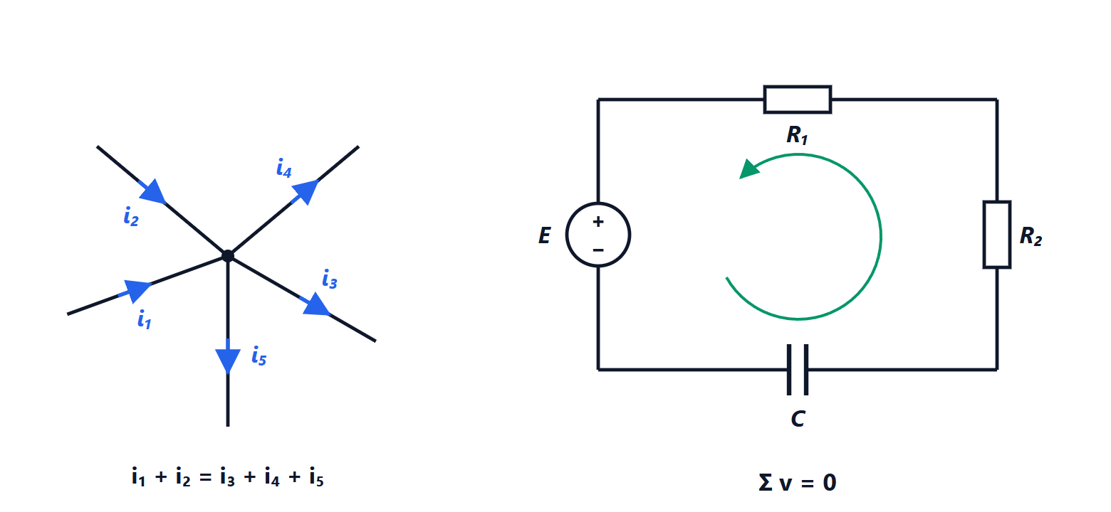
The bridge compares the unknown resistance with standard resistances instead of measuring voltages and currents. Four resistances form two dividers supplied by the same voltage  : on the left
 on top and
 below, on the right
 on top and below. A null detector (a galvanometer or a sensitive voltmeter) connects the midpoints A and B.
Theorem (balance). The detector reads zero if and only if
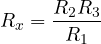
Proof. With the detector drawing no current, the two arms are independent dividers:

A null means  , i.e.
 . Expanding, the term
 appears on both sides and cancels:
 remains, which gives the formula. The steps can be reversed, so the condition is also sufficient. ∎
The result depends neither on nor on the detector: the supply voltage may vary and the detector may be uncalibrated, as long as it can recognise zero. The uncertainty depends only on that of the standard resistances and on the sensitivity with which the null is seen. That is why bridges were for a century the reference method in calibration laboratories. In manual bridges is a decade box and the ratio  is a power-of-ten multiplier.
The unbalanced bridge and its sensitivity
Often the bridge is not rebalanced: the unbalance voltage is read, which follows small changes of . This is how strain gauges and many sensors work (lesson on sensors).
Theorem. With all resistances equal to  and
 , the output voltage is

Proof.  , while
 . The difference is

and for small  the denominator is about 4. ∎
The relation is almost linear for small changes: with  the linearity error is 0.5 %. With
 V and
 the output is about 1.25 mV: small signals, requiring an accurate differential amplifier.
AC bridges
With a sinusoidal supply and impedances instead of resistances, the same reasoning leads to the balance condition

Being an equality between complex numbers, it amounts to two conditions (real and imaginary part, or magnitude and phase): two independent adjustments are needed, and balance is reached by alternating them. This is the origin of the classic bridges for measuring capacitors with their losses and inductors with their resistance. The Maxwell bridge, for instance, measures a real inductor by comparing it with a standard capacitor, more stable and accurate than any standard inductor. Today automatic LCR meters do the same job: they measure voltage and current in magnitude and phase with synchronous demodulation and compute the impedance.
Very large resistances
Above gigaohms the problem is reversed: currents are picoamperes and leakage currents over the surfaces of insulators and cables can exceed the one being measured. Electrometers with a guard ring are used: a conductor held at the same potential as the measurement point, which intercepts the surface currents. Insulation testers (megohmmeters) apply hundreds or thousands of volts to check the insulation of cables, motors and installations.