Shielding: absorption, reflection and apertures
Shielding effectiveness, absorption 8.69 t/δ and reflection proved with copper examples, low-frequency magnetic fields, slots and cables passing through the shield.
A shield is a conductive enclosure separating the source from the victim: a device’s metal case, a cable’s braid, a foil over a sensitive circuit. It works in two ways, reflecting the wave and absorbing it, and the calculations show that even a very thin foil would suffice for most fields. The real problem is apertures: slots, seams and cables passing through the shield. In this lesson we look at shielding effectiveness, absorption and reflection with their proofs and examples, the difficult case of low-frequency magnetic fields, and apertures.
Shielding effectiveness
Shielding effectiveness is the ratio, in decibels, between the field without the shield and with it:
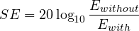
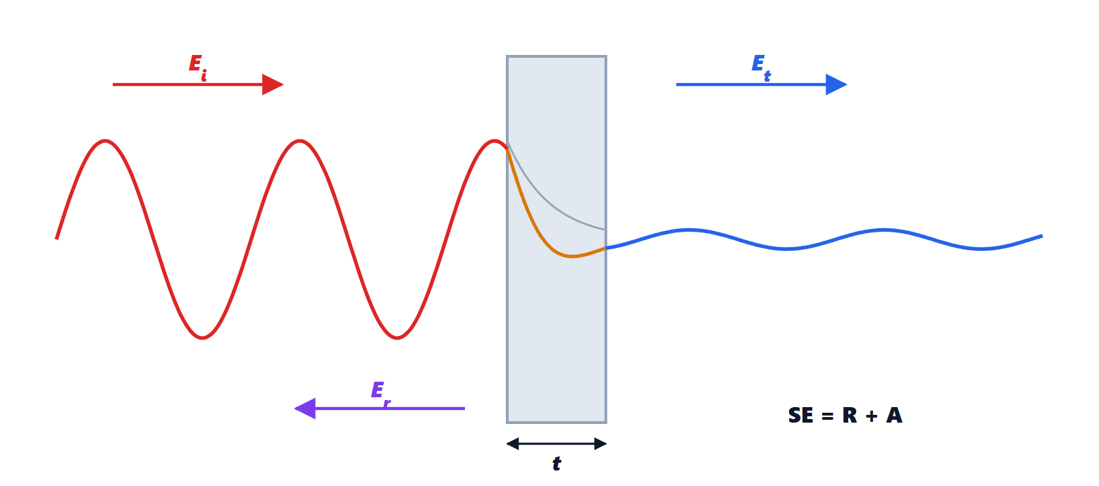
According to Schelkunoff’s theory it splits into three terms:  , reflection, absorption and a correction term for multiple reflections inside the shield, negligible when absorption exceeds about ten decibels.
Absorption
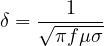
Inside a good conductor the field decays exponentially with depth, with a characteristic length called the skin depth (Electromagnetic Fields lesson on the skin effect):
Theorem. A shield of thickness  introduces an absorption of
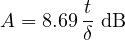
Proof. Crossing the thickness , the field amplitude is reduced by the factor  . In decibels:
 . ∎
Example. Copper,  S/m: at 1 MHz
 µm, and a 0.1 mm foil absorbs about 13 dB; at 100 MHz
 µm and the same foil absorbs about 130 dB. Absorption grows with the square root of frequency: at high frequencies even a thin metal layer deposited on plastic is enough.
Reflection
A wave reaching a surface with an impedance different from its own is largely reflected (lesson on plane waves). The wave in free space has impedance  Ω, the metal a very small impedance,
 .
Theorem. For  the reflection is
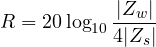
Proof. The transmission coefficient of the electric field from a medium of impedance  to one of impedance
 is
 . Entering the metal it is
 ; leaving it,
 . The product is
 , and its inverse in decibels gives the formula. ∎
Example. Copper at 1 MHz:  Ω,
 dB. With absorption, even a thin copper shield gives more than 120 dB against a plane wave: far more than is needed.
The difficult case: near magnetic fields
Close to a magnetic source (a loop, a transformer) the wave impedance is much lower than 377 Ω, and reflection is reduced accordingly; at low frequency absorption is also small, because  is large (at 50 Hz in copper it is about 9 mm). A mains transformer cannot be shielded with a copper foil. What is needed is:
- high-permeability materials (iron-nickel alloys such as mu-metal), which offer the field lines a preferential path and divert them around the area to be protected;
- or, better, reducing the source and the victim loop (lesson on coupling).
Near electric fields, on the contrary, with high impedance, are easily shielded: a grounded conductive surface is enough.
Apertures
In practice a shield is never closed: there are ventilation slots, seams between panels, displays, connectors. A slot behaves like a slot antenna (lesson on aperture antennas), and what matters is its maximum dimension, not its area. For a slot of length  , less than half a wavelength:
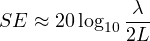
Example. A 10 cm slot at 1 GHz ( cm) leaves only 3.5 dB of shielding; at 100 MHz, 23.5 dB. The thickness and material of the shield become irrelevant: the slot is what counts. Many small holes shield much better than a slot of the same area, because each has a small maximum dimension.
The resulting rules:
- seams with frequent contacts (closely spaced screws, conductive gaskets), at a spacing much less than
 at the highest frequency of interest;
- ventilation with grids of small holes or honeycombs, which behave like waveguides below cut-off;
- every cable passing through the shield must be filtered at the point of entry, or its braid must be bonded to the shield around its whole circumference (360°). An unfiltered cable carries the disturbance outside and radiates it, defeating the shield: it is the most common mistake. A braid connected with a short wire (pigtail) loses much of its effectiveness at high frequencies, because the pigtail has inductance.