Immunity: electrostatic discharge, transients and fields
IEC 61000-4 tests and performance criteria, current and energy of an electrostatic discharge, why the TVS goes next to the connector (proved), rectification of radio frequency, software defences.
The other half of compatibility is immunity: the device must keep working when someone touches it after walking on a carpet, when a phone transmits nearby, when a motor on the same line switches off or lightning strikes a few hundred metres away. In this lesson we look at immunity tests and the criteria used to judge the result, electrostatic discharge with the calculation of its current and energy, input protection with the proof of why connections must be very short, the rectification of radio-frequency fields and software defences.
The tests
The IEC 61000-4 series defines the phenomena and the test generators. The most common:
| Test | Phenomenon | Typical levels |
|---|---|---|
| 61000-4-2 | electrostatic discharge | 4 kV contact, 8 kV air |
| 61000-4-3 | radiated field, 80 MHz – 6 GHz, AM modulated at 1 kHz | 3 V/m (residential), 10 V/m (industrial) |
| 61000-4-4 | bursts of fast transients (5 ns edges), from contacts and relays | 1-2 kV on the supply |
| 61000-4-5 | surges from lightning and switching, 1.2/50 µs | 1-2 kV |
| 61000-4-6 | radio-frequency disturbances conducted on cables, 150 kHz – 80 MHz | 3-10 V |
| 61000-4-11 | voltage dips and interruptions | from 30 % to 100 % for a few cycles |
The result is judged with three criteria: A, normal operation during the test; B, temporary degradation with self-recovery; C, loss of function requiring operator intervention. The product standard establishes which criterion is required for each test.
Electrostatic discharge
A person insulated from the floor charges up by friction to thousands of volts. The human body model (HBM) represents it as a 100 pF capacitor discharging through 1.5 kΩ; the IEC test generator uses 150 pF and 330 Ω, more severe because it represents a discharge through a metal object held in the hand.
Theorem. A capacitor  charged to voltage
 discharging into a resistance
 gives a peak current
 , a time constant
 and an energy
 .
Proof. At the initial instant the whole capacitor voltage is across the resistance, so  . Then
 , with solution
 . The dissipated energy is the energy stored in the capacitor, . ∎
Example. IEC generator at 8 kV: peak current of the order of  A (the standard specifies a first peak of about 30 A, because the initial edge, under a nanosecond, is limited by inductance and not by resistance), time constant about 50 ns, energy
 mJ. The energy is small, but the current is huge and the very fast edge has a spectrum reaching the gigahertz range: the discharge also disturbs, by coupling, circuits it does not touch directly.
Protecting an input
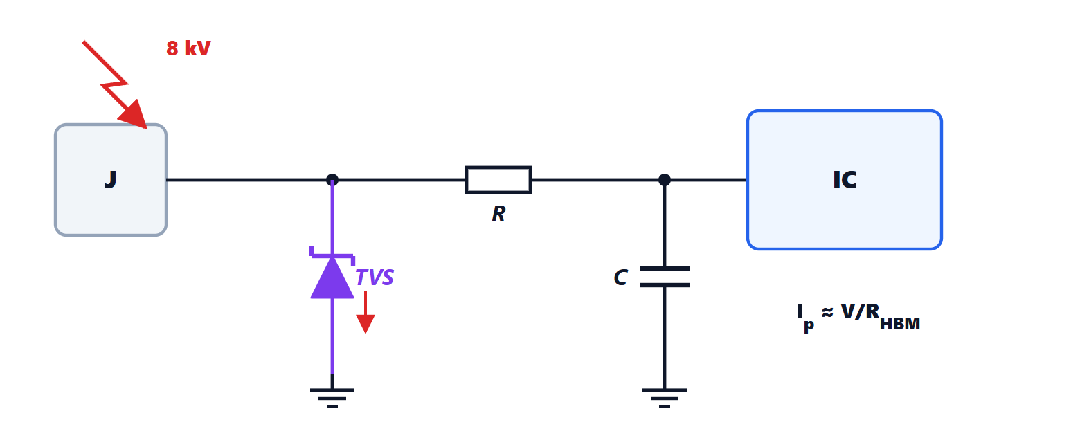
The classic scheme has a transient voltage suppressor diode (TVS) right after the connector, which conducts above a threshold voltage and diverts the current to ground, followed by a series resistor and a small capacitor that limit the residue before the integrated circuit, which in turn has weak internal protections (Microelectronics lesson on testing).
Theorem. With a connection of inductance  in series with the TVS, the voltage on the protected input during the discharge exceeds the diode’s clamping voltage by
 .
Proof. The discharge current flows in the TVS branch, made of the diode and its connections. The branch voltage is the sum of the diode voltage and the voltage across the inductance, , and this is the voltage seen by the protected node. ∎
Example. 10 nH of connection (one centimetre of trace to a distant ground) and a current rising to 30 A in 1 ns:  V above the clamping voltage. The protection does not protect. The TVS must be placed right next to the connector, with the shortest possible ground connection, preferably directly to the chassis, so that the discharge does not cross the circuit’s ground plane.
For slow, energetic overvoltages (surges) more robust components are needed: metal-oxide varistors, gas discharge tubes, often in several stages.
Radio-frequency fields and rectification
A radiated field induces radio-frequency voltages on cables (lesson on radiated emissions, by reciprocity). This would seem harmless to a slow circuit, such as an audio or sensor amplifier, which has no bandwidth at those frequencies. But transistor junctions are non-linear: they rectify the radio frequency, and the 1 kHz AM modulation used in the test reappears as a 1 kHz signal in the useful band. It is the buzz heard in a loudspeaker near a phone transmitting in bursts.
Remedy: filter the radio frequency before it reaches the first junction, with an RC filter or a ferrite and a capacitor right at the input.
Software defences
Not everything is stopped by hardware. A good program tolerates disturbances:
- watchdog: a timer that restarts the processor if the program stops refreshing it;
- periodic re-reading of peripheral configuration registers, which a discharge can alter;
- filters and plausibility checks on inputs, confirmation of a command over several samples (debouncing);
- check codes (CRC) on communications and memories, with retransmission;
- predefined safe states for outputs in case of error.
This lesson completes the picture: reduce the source, interrupt the path, make the victim robust.