Capacitive, inductive and common-impedance coupling
Capacitive crosstalk voltage proved, wire-loop mutual inductance proved, numerical examples, twisted pair, ground bounce, how to recognise the mechanism.
At distances small compared with the wavelength, that is inside a device, on a printed circuit board or between nearby cables, disturbances travel along three routes that are studied with ordinary circuits: parasitic capacitance, mutual inductance and common impedance. In this lesson we derive the induced voltage in each case with a numerical example, and look at the remedies: distance, impedances, shields, twisted pairs and well-made grounds.
Capacitive coupling
Two nearby conductors form a capacitance  . If conductor 1 has a varying voltage
 , the capacitance injects a current into conductor 2, which discharges it to ground through its impedance: the resistance
 of the connected circuits and the capacitance to ground
 .
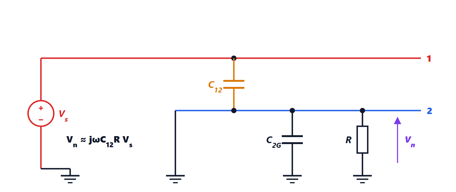
Theorem. The voltage induced on conductor 2 is

which at low frequencies is about  and at high frequencies tends to
 .
Proof. Kirchhoff’s current law at node 2: the current entering through equals the current leaving to ground through and :

Multiplying by and solving for  gives the formula. If
 the denominator is about 1; if it is
 the
 terms cancel and the capacitive divider remains. ∎
The noise, in the most common region, grows with frequency (more precisely with edge speed), with the capacitance and with the victim’s impedance.
Example. A 10 MHz, 3.3 V clock runs close to the input of a high-impedance sensor,  kΩ, with
 pF.
 , so
 V: a disaster for a sensor. With
 Ω the noise drops to about 21 mV.
Remedies: increase the distance (the capacitance falls), reduce the victim’s impedance, place between the two conductors a trace or a grounded shield, which intercepts the electric field lines. A shield not connected to ground is useless: it charges to an intermediate voltage and passes the disturbance on.
Inductive coupling
A varying current  in conductor 1 produces a magnetic field, whose flux through the loop formed by the victim circuit induces a voltage
 , or in time
 (Physics 2 lesson on induction).
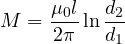
Theorem. A long straight wire and a coplanar rectangular loop of length  , with sides parallel to the wire at distances
 and
 , have mutual inductance
Proof. The wire’s field at distance  is
 (Ampère’s law). The flux through the loop is the integral of
 over its area, in strips of width
 and length :

and  . ∎
Example. A cable carrying a motor current runs close to a measurement circuit:  cm,
 cm,
 cm.
 nH. If the current changes by 10 A in 100 ns (a power switch),
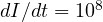 A/s and
 V.
Remedies: increase the distance, and above all reduce the area of the victim loop, bringing the return wire close to the outgoing one. The twisted pair does even better: at every half twist the two wires swap places and the orientation of the small loop is reversed, so the voltages induced in successive loops have opposite signs and cancel. Against low-frequency magnetic fields (50 Hz, transformers) copper shields are of little use; high-permeability materials are needed (lesson on shielding).
Common impedance
If two circuits share a stretch of conductor, for example the ground return, the current of the first produces across that stretch a drop  that adds to the signals of the second. At digital signal frequencies inductance dominates: a thin trace has about 1 nH per millimetre.
Example. A logic output draws 50 mA in 1 ns through 5 nH of shared ground:  V. This is ground bounce, which can make a nearby logic input switch by mistake or corrupt a converter’s measurement.
Remedies: separate grounds joined at a single point for low-frequency circuits (star ground), a continuous ground plane for fast ones, which offers every current a very low-inductance return (lesson on printed circuit board design), and decoupling capacitors close to the components, which supply the current peaks locally.
Recognising the mechanism
To diagnose a problem it helps to ask which quantity of the source matters: if the noise scales with  and is sensitive to the victim’s impedance, it is capacitive; if it scales with
 and depends on loop area, it is inductive; if it appears only when another circuit draws current, it is a common impedance. The simplest test: change the victim’s impedance. If the noise falls when the impedance is lowered it is capacitive; if it stays about the same it is inductive, because the induced voltage is a source in series with the loop, which depends on the area and not on the impedance.