Conducted emissions and mains filters
Artificial network and limits, the origin of common-mode noise in power supplies, the common-mode choke proved, LC filter attenuation, Y capacitor leakage current.
Switching power supplies are efficient and small, but they switch hundreds of volts in tens of nanoseconds, and send disturbances back onto the mains. Standards limit these conducted emissions between 150 kHz and 30 MHz, and almost every mains-powered device has a mains filter at its input. In this lesson we look at how conducted emissions are measured, the difference between differential-mode and common-mode disturbances with an example of their origin, how the common-mode choke works with its proof, the attenuation of an LC filter, and the safety limit on capacitors to earth.
Measurement
The conducted disturbance depends on the mains impedance, which changes from one socket to another. To make the measurement repeatable, an artificial network (LISN, line impedance stabilization network) is inserted between mains and device: for each conductor it presents the device with a defined impedance, 50 Ω in parallel with 50 µH, blocks disturbances coming from the mains and sends those of the device to a measuring receiver.
The CISPR 32 limits for class B, with the quasi-peak detector, are about 66-56 dBµV between 150 and 500 kHz (decreasing), 56 dBµV up to 5 MHz and 60 dBµV up to 30 MHz; for the average detector they are 10 dB lower.
Differential mode and common mode
As for cables (lesson on radiated emissions), the disturbance on the line (L) and neutral (N) conductors splits into two parts, with different origins and remedies:
- differential mode: current going out on L and back on N. It arises from the pulsating current drawn by the power supply, which the input capacitor cannot fully provide;
- common mode: current going on L and N in the same direction and returning through the protective earth conductor (PE) or capacitances to earth. It arises from the fast voltage changes of the switching node, which push current through parasitic capacitances, for example the one between the transistor and the earthed heatsink.
Example. The switching node goes from 0 to 400 V in 50 ns, and the transistor has 50 pF to the earthed heatsink. The current  A flows in pulses to earth at every transition: a huge common-mode disturbance, which the filter must block. An insulating pad with a shield connected to the primary reference, or a heatsink not connected to earth, reduces it at the source.
The mains filter
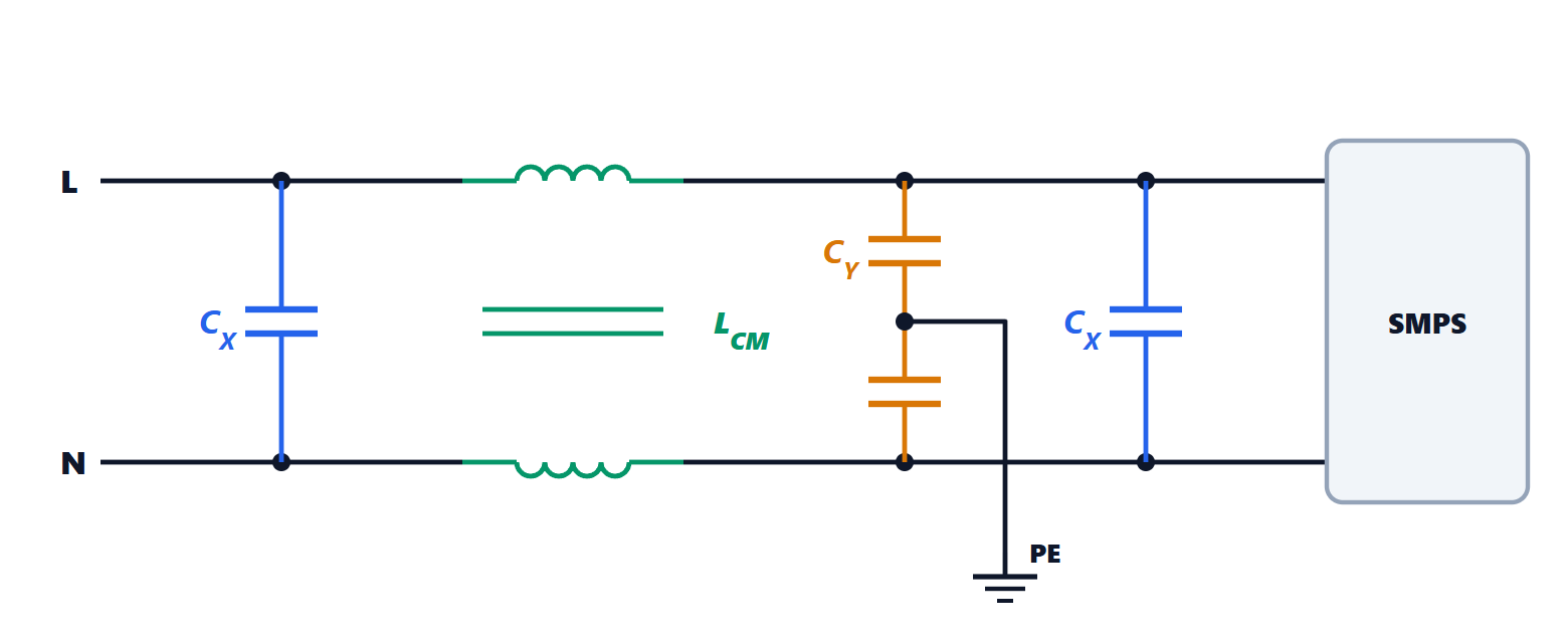
The typical filter has:
- X capacitors between L and N, against differential mode: they offer a short circuit at high frequencies to the current that goes and returns;
- a common-mode choke: two identical windings on the same core, one on L and one on N;
- Y capacitors from L and from N to earth, which close the common-mode current locally.
Theorem. In an ideal common-mode choke the differential-mode current produces no flux in the core, while the common-mode current sees the full inductance.
Proof. The two windings have the same number of turns  and are wound so that currents in the same direction produce aiding fluxes. The flux in the core is proportional to the sum of the magnetomotive forces:
 . In differential mode
 and
 : no induced voltage, no impedance. In common mode
 and the fluxes add. ∎
The advantage is decisive: the mains current, which can be many amperes, does not magnetise the core, which therefore does not saturate, and small high-permeability ferrite cores can be used to obtain millihenries of common-mode inductance. A small leakage flux, not linking both windings, still gives some differential-mode inductance, useful together with the X capacitors.
Attenuation
Each section formed by an inductor and a capacitor is a second-order low-pass filter.
Theorem. An ideal LC filter, terminated on a high-impedance load, has transfer function  with
 , and above
 attenuates by 40 dB per decade.
Proof. It is a divider between the inductor’s impedance  and the capacitor’s
 :
 . For
 the magnitude is about
 , which falls by a factor of 100, i.e. 40 dB, every decade. ∎
Example. With  kHz the attenuation at 150 kHz is about
 dB. In reality the attenuation depends on the impedances of the mains and of the power supply, and at high frequencies it is limited by parasitics: the inter-winding capacitance of the choke and the inductance of the capacitor connections. This is why filters are mounted close to the cable entry point, with input and output well separated, because coupling between the two bypasses the filter.
The safety limit on Y capacitors
Y capacitors also carry a small 50 Hz current to earth, the leakage current, which would flow through a person if the earth connection were missing. It is  .
Example. With 4.7 nF to earth and 230 V at 50 Hz:  mA. Safety standards limit leakage to values from a few tenths of a milliampere to a few milliamperes depending on the type of equipment (much less for medical equipment), and therefore limit Y capacitors to a few nanofarads. Common mode must be fought mainly with the choke.
Capacitors connected to the mains must also be of an approved type: X capacitors are designed not to fail short-circuit if a surge damages them, Y capacitors never to fail short-circuit to earth, because they would put the mains voltage on the chassis.




