Electromagnetic compatibility: source, path, victim and standards
Emissions and immunity, the four coupling mechanisms, near and far field, dBµV and dBm with the conversion proved, antenna factor, CISPR and IEC 61000 standards.
An electronic device is electromagnetically compatible if it works correctly in its electromagnetic environment without introducing intolerable disturbances for others. These are two requirements: not disturbing (limiting emissions) and not being disturbed (having sufficient immunity). In this lesson we look at the source-path-victim model and the four coupling mechanisms, the decibel units used in measurements with the proof of the conversion between dBµV and dBm, and the framework of standards.
Source, path, victim
Every compatibility problem has three elements: a source of disturbance (a clock, a switching power supply, a motor, a radio transmitter, an electrostatic discharge), a victim (a receiver, a sensor amplifier, a logic input) and a path connecting them. To solve it, it is enough to act on one of the three: reduce the source, interrupt the path or make the victim less sensitive. Acting on the source is usually the cheapest solution, because the intervention is at a single point instead of on all possible victims.
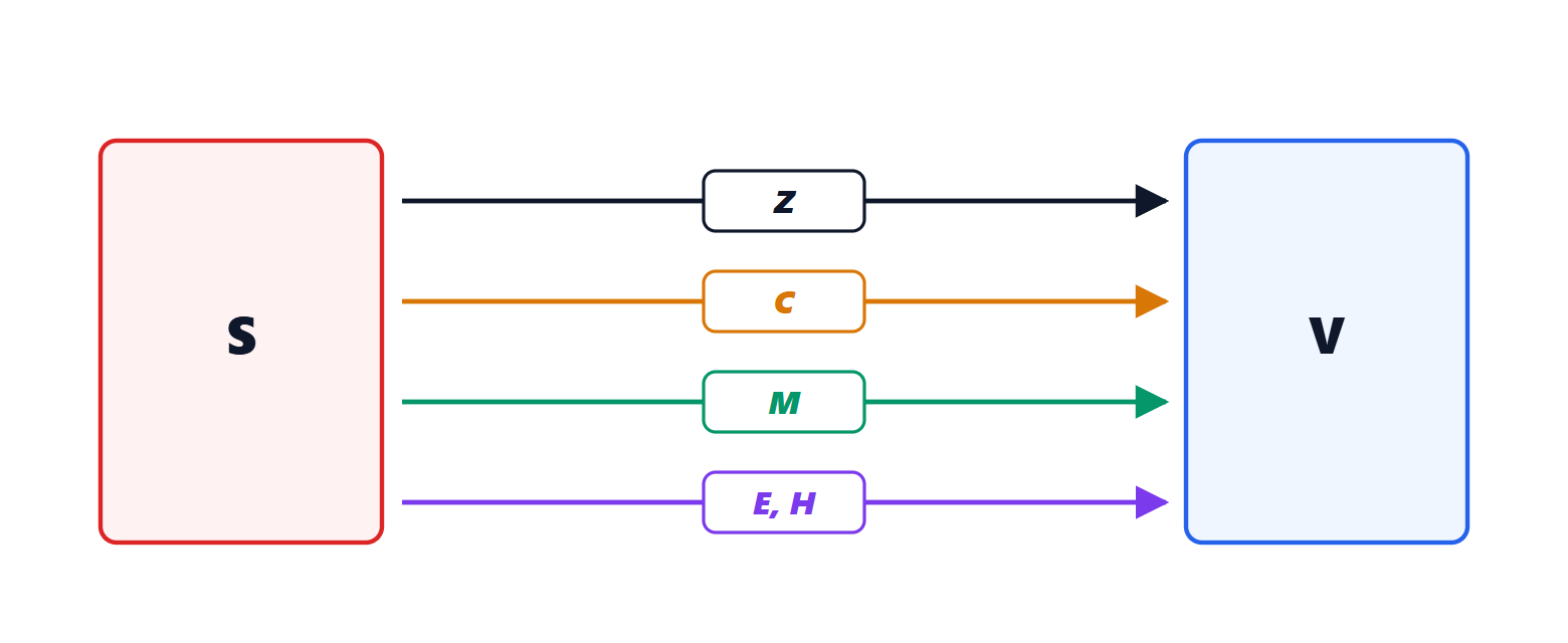
There are four paths:
- conduction through a common impedance: two circuits sharing a stretch of ground or supply; the current of one produces a drop that appears in the other;
- capacitive coupling (electric field): a parasitic capacitance between two nearby conductors, dominant when the source has high voltages and fast changes;
- inductive coupling (magnetic field): a mutual inductance between two loops, dominant when the source has large currents and fast changes;
- radiation: at large distance compared with the wavelength, electric and magnetic fields travel together as a wave (Electromagnetic Fields and Antennas lessons).
The first three are near-field and are analysed with lumped circuits (lesson on coupling); the last is far-field. The boundary is at about  : at 100 MHz about 48 cm.
Emissions and immunity are also divided into conducted (disturbances travel on cables, typically below 30 MHz, where cables are short compared with the wavelength and radiate little) and radiated (above 30 MHz).
The decibels of compatibility
Disturbances span many orders of magnitude and are measured in decibels relative to small references:
- voltages in dBµV:
 ; 1 mV is 60 dBµV;
- electric fields in dBµV/m;
- currents in dBµA;
- powers in dBm, relative to 1 mW.
Theorem. On a 50 Ω impedance, power in dBm and voltage in dBµV are related by

Proof. Power is  . A voltage of 1 µV on 50 Ω gives
 W
 mW, i.e.
 dBm. Since
 and
 grow in the same way, the difference stays constant for any voltage. ∎
Spectrum analysers, which have a 50 Ω input, display dBm; standards set limits in dBµV: the conversion is needed in every measurement.
Example. A disturbance of  dBm read on the analyser corresponds to
 dBµV, i.e. about 224 µV.
To go from the voltage at the measuring antenna’s terminals to the field, the antenna factor  (in dB/m), provided by the manufacturer, is used:
 , plus the cable losses.
Standards
In Europe the CE marking requires, among other things, compliance with the electromagnetic compatibility directive; in the United States the FCC rules apply. Technical standards set the limits and test methods:
- emissions: for multimedia and IT equipment the CISPR 32 standard (in Europe EN 55032) sets, for household equipment (class B), about 30 dBµV/m at 10 m between 30 and 230 MHz and 37 dBµV/m between 230 MHz and 1 GHz; for industrial equipment (class A) the limits are about 10 dB higher. For conducted emissions on the mains the limits apply between 150 kHz and 30 MHz;
- immunity: the IEC 61000-4 series defines the tests against electrostatic discharges, radiated fields, fast transients, surges and conducted disturbances (lesson on immunity).
Tests are carried out in accredited laboratories, in semi-anechoic chambers, but it pays to check compatibility from the design stage: a problem discovered at the final test costs weeks and a new revision of the printed circuit board. The following lessons show how to predict and control emissions: the spectrum of digital signals, coupling, shielding, radiation from loops and cables, printed circuit board design, filters and protection.