Sinusoidal steady state: phasors and impedance
Why sinusoids, the phasor and its operations, impedance and admittance of resistor, inductor and capacitor, a complete example and the phasor method step by step.
The relations between voltage and current in two-terminal elements hold at every instant. With constant quantities they are written with algebra; when quantities vary in time, capacitors and inductors bring in derivatives, and the circuit equations become differential. There is, however, one case, the most important of all, in which you return to algebra: when every source is sinusoidal at the same frequency and the circuit has reached steady state. With complex numbers, phasors, derivatives become multiplications and all the methods for resistive circuits apply again. It is the language of the 50 Hz power grid, of audio and of radio.
Why sinusoids
In a linear circuit, if every source is sinusoidal with angular frequency  , at steady state every voltage and current is a sinusoid with the same angular frequency: only amplitude and phase change. The reason is that differentiating or integrating a sinusoid gives another sinusoid of the same frequency, shifted by 90°. Moreover, by Fourier series and transforms, any signal is a sum of sinusoids: knowing the response to a sinusoid of any frequency means being able to compute the response to any signal.
The phasor
A sinusoid  is determined, once is known, by two numbers: amplitude and phase. They are gathered into a single complex number, the phasor:

In circuit theory the letter  is used for the imaginary unit (
 is reserved for current) and the phasor’s magnitude is usually the RMS value
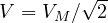 , so that the power formulas have no
 factors.
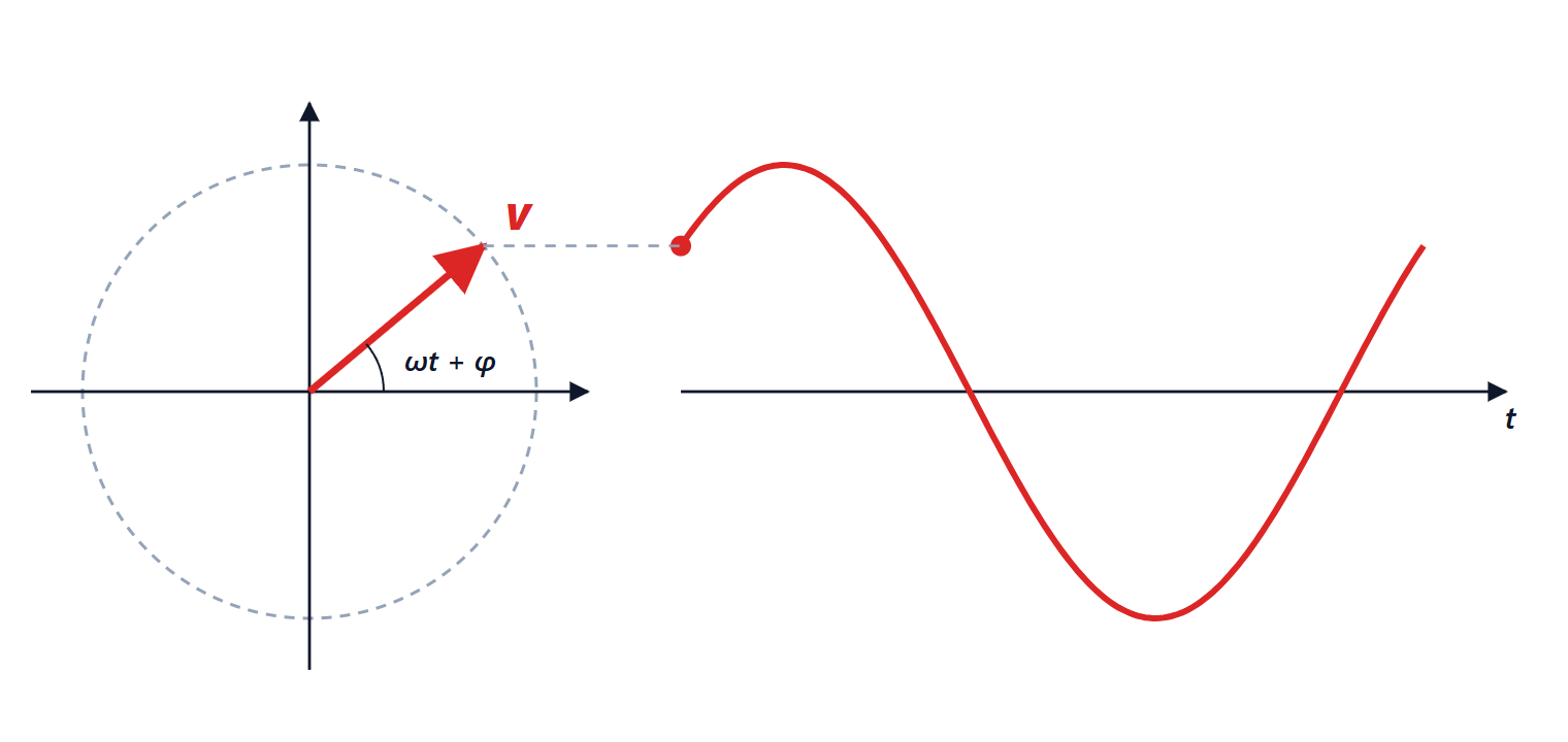
Operations. Adding sinusoids of the same frequency means adding their phasors as vectors, with the parallelogram rule. Differentiating means multiplying the phasor by  (amplitude times , phase advanced by 90°); integrating means dividing by .
Example.  and
 : the phasors are
 and
 , the sum
 , that is
 . Adding the amplitudes would have given 20: wrong, because the peaks do not occur at the same instant.
Impedance and admittance
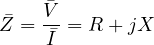
For each element the ratio of the voltage phasor to the current phasor is the impedance:
| Element | Impedance | Voltage-current phase shift |
|---|---|---|
| resistor |  | 0 |
| inductor |  | +90° (voltage leads) |
| capacitor | 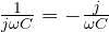 | −90° (voltage lags) |
The real part is the resistance, the imaginary part  the reactance: positive for inductive behaviour, negative for capacitive. The inverse of impedance is admittance
 , handy for parallel connections.
With impedances all the results for resistive circuits hold: Kirchhoff’s laws for phasors, series and parallel, dividers, nodal analysis, superposition, Thevenin and Norton. You just work with complex numbers.
A complete example
A 230 V, 50 Hz source feeds a resistance  Ω in series with an inductor
 mH. The reactance is
 Ω, so

The current has an RMS value of  A and lags the voltage by 53.1°:

The voltages across the components are  V and
 V. Added as magnitudes they would give 322 V, more than the source’s 230 V: it looks like a paradox, but the two phasors are 90° apart, and indeed
 .
The method in practice
- Choose a phase reference (usually a source at zero phase).
- Replace the sources with their phasors and the components with their impedances at angular frequency .
- Solve the circuit with the methods for resistive circuits, in complex arithmetic.
- Go back to time:
 becomes
 .
Careful: the method holds only at steady state and with sources of the same frequency. With different frequencies you solve one circuit per frequency and add the results in time (superposition), never the phasors. Transients need the methods of the previous lesson or the Laplace transform.
The following lessons apply this method to power in sinusoidal steady state, to frequency response and to three-phase systems.