Power in sinusoidal steady state: active, reactive, apparent and power factor correction
Instantaneous power, active, reactive and apparent power, complex power, Boucherot's theorem, power factor, power factor correction calculation and PFC in power supplies.
In DC, power is simply voltage times current. In sinusoidal steady state voltage and current are out of phase, and their product oscillates: part of the energy is really consumed, part goes back and forth between the source and the reactive components without doing useful work. Telling the two apart is essential for sizing cables and transformers, for understanding an industrial electricity bill and for designing power supplies. In this lesson we cover active, reactive and apparent power, the power factor and power factor correction.
Instantaneous power
With  and
 , using the product-to-sum formula:

Instantaneous power has a constant average plus a term oscillating at twice the frequency. In a resistor ( ) it is always positive; in an ideal inductor or capacitor (
 ) its average is zero: energy flows in while the field builds up and flows out while it collapses.
Active, reactive and apparent power
- Active power
 , in watts (W): the average, the energy actually turned into heat, mechanical work or light. It is what the household meter measures.
- Reactive power
 , in volt-amperes reactive (VAR): the size of the energy exchange with electric and magnetic fields. Positive for inductive loads, negative for capacitive ones.
- Apparent power
 , in volt-amperes (VA): the product of the RMS values, which sizes cables, transformers and generators, because currents heat them regardless of the phase shift.
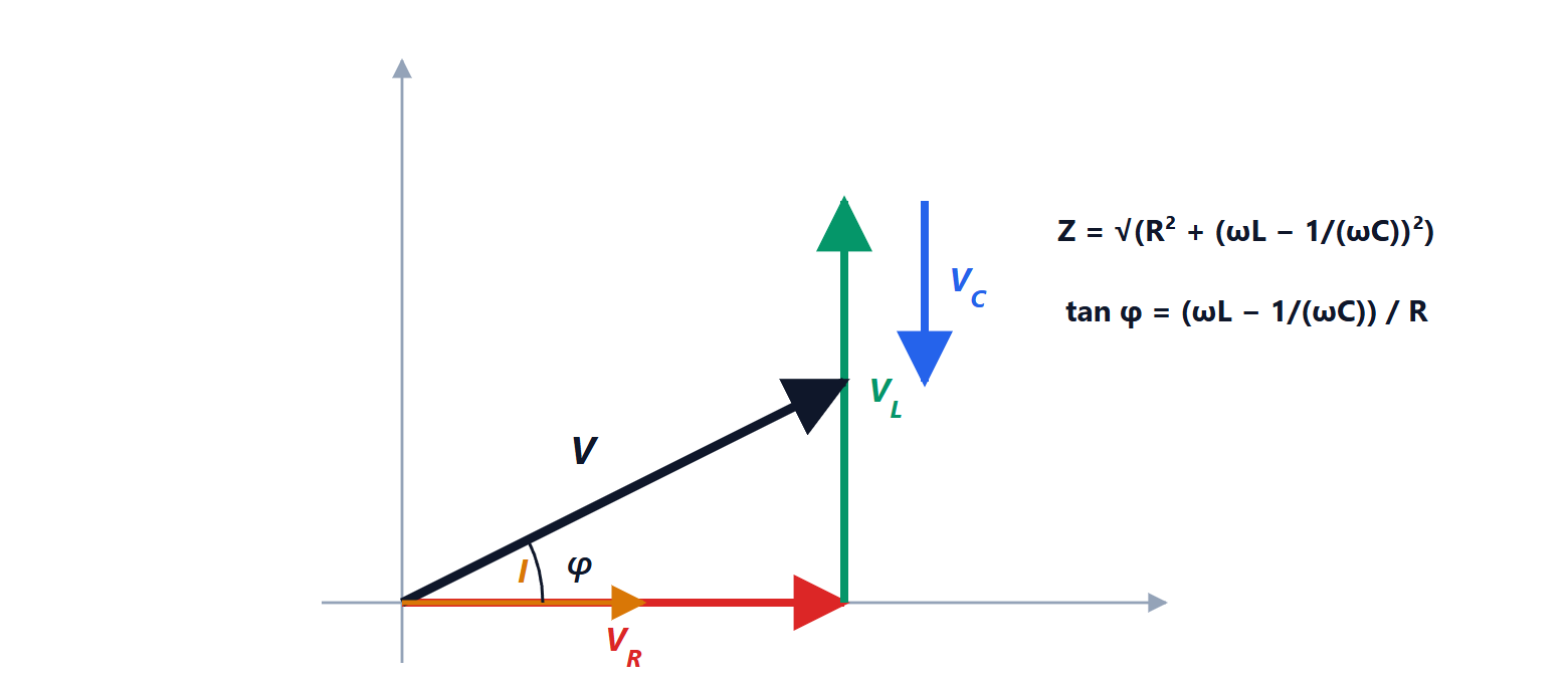
The three quantities form the power triangle:  . In complex form the complex power is

where  is the conjugate of the current phasor. For an impedance
 :
 ,
 .
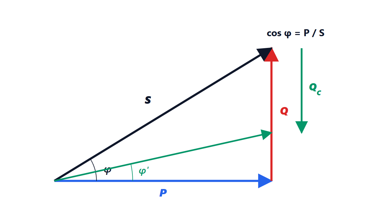
Conservation (Boucherot’s theorem). In a circuit, the total active power absorbed by the loads equals that delivered by the sources, and the same holds separately for reactive powers. Apparent powers, however, do not add up.
The power factor

tells what fraction of the apparent power is useful. A resistor has a factor of 1, an induction motor at half load can drop to 0.5 to 0.7.
Why it matters. A motor drawing  kW at 400 V single phase (for simplicity): with
 the current is 25 A, with
 it rises to 41.7 A. Cable losses,
 , grow by
 , that is 2.8 times, and cables and transformers must be sized for the higher current. That is why utilities charge customers with a low power factor for reactive energy: in Italy, for medium and low voltage users above a certain power, below 0.95.
Power factor correction
An inductive load absorbs positive reactive power. A capacitor in parallel supplies negative reactive power,  , and the grid has to provide only the difference. The active power does not change.
The calculation
To bring a load from  to
 at the same
 , the reactive power must drop from
 to
 . The capacitor must supply

Example. A workshop draws 20 kW at 230 V, 50 Hz with  (
 ). To reach 0.95 (
 ) it needs
 kVAR, that is
 µF (a real three-phase installation uses 400 V capacitor banks, which are smaller). The current falls from 124 A to 91.5 A.
It is not worth correcting all the way to 1: the capacitor would cost far more for a small gain, and with a varying load you would risk becoming capacitive.
The power factor of power supplies
Modern electronic loads pose a different problem: a supply with a rectifier and a capacitor draws current only in short peaks near the voltage maximum. The current is not shifted but distorted, full of harmonics, and even so the power factor (defined as  ) is low, around 0.5 to 0.6. A capacitor does not help: an active power factor correction (PFC) circuit is used, a converter that forces the current to follow the sinusoidal shape of the voltage. European standards make it mandatory for equipment above 75 W, which is why computer power supplies state a power factor of 0.99.