Controlled rectifiers, HVDC and power factor correction
The diode rectifier and harmonics, the thyristor bridge with mean voltage proved, inverter operation, six- and twelve-pulse three-phase bridges, HVDC, the PFC stage.
Almost every electronic appliance starts with a rectifier that turns the mains AC voltage into DC. At high powers, from industrial furnaces to DC transmission lines, the rectifier is also controlled, and regulates the output voltage. In this lesson we look at the diode rectifier with a capacitor and its harmonics problem, the thyristor-controlled bridge with the proof of the mean voltage as a function of the firing angle, inverter operation, the three-phase bridge and power factor correction.
The diode rectifier with a capacitor
The most common circuit is a bridge of four diodes followed by a smoothing capacitor (Electronic Devices lesson on diode circuits). The capacitor charges only near the peaks of the sine wave, when the mains voltage exceeds its own: the current drawn from the mains consists of narrow, tall pulses, one per half-cycle. The spectrum of this current is rich in odd harmonics (third, fifth, seventh), and the power factor is low, typically 0.5-0.7, even though the fundamental is almost in phase with the voltage (Electrical Measurements lesson on power measurement). Millions of such appliances distort the mains voltage and overload neutral conductors, where the third harmonics of the three phases add up instead of cancelling.
The controlled bridge
Replacing the diodes with thyristors, each conducts only from the moment it receives its firing pulse. The firing instant is measured by the delay angle  , counted from the point at which the voltage across the thyristor becomes positive. With a strongly inductive load (a DC motor, an electromagnet) the current is practically constant and continuous, and each pair of thyristors conducts for half a period, from to
 , even when the mains voltage has already become negative.
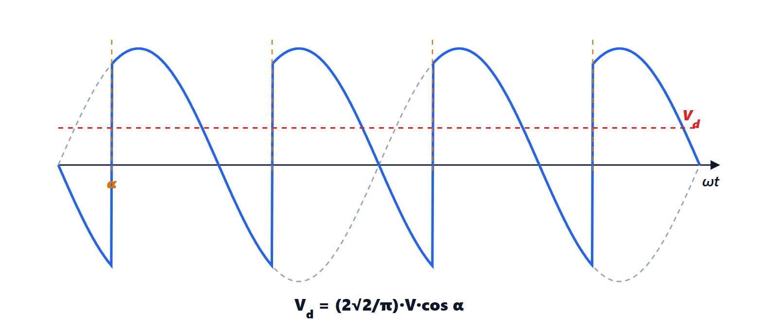
Theorem. With mains voltage of RMS value  and continuous current, the mean output voltage of the single-phase controlled bridge is
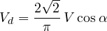
Proof. In each half-period the output equals  for
 from to . The mean value is

because  . ∎
With  the diode rectifier is recovered,
 ; increasing the mean voltage falls with the cosine.
Inverter operation
For  the cosine is negative and the mean output voltage changes sign, while the current, imposed by the thyristors, keeps the same direction: the mean power
 becomes negative and flows from the DC side to the mains. The converter works as a “line-commutated” inverter. This is how a DC drive brakes a train or a lift by returning energy (regenerative braking), and how the receiving stations of DC transmission lines work.
The three-phase bridge
At high powers the three-phase six-thyristor bridge is used, drawing current from all three phases. The output consists of six caps per period (a six-pulse rectifier), with much smaller ripple, and the mean value, with the same calculation extended over a sixth of a period, is

with  the line-to-line voltage. The harmonics of the mains current are only those of order
 (5, 7, 11, 13…). Putting two bridges in series fed by transformers shifted by 30° gives a twelve-pulse rectifier, which also cancels the fifth and seventh. This is the structure of the converter stations of HVDC lines (high-voltage direct current transmission), which carry gigawatts over thousands of kilometres or under the sea with lower losses than alternating current.
Power factor correction
Standards (such as IEC 61000-3-2) limit the current harmonics of appliances above a few tens of watts. The solution is the power factor correction (PFC) stage: a boost converter (lesson on DC-DC converters) placed right after the diode bridge, with no large capacitor upstream. Its control makes the inductor current, and hence the current drawn from the mains, follow instant by instant the sinusoidal shape of the rectified voltage, with an amplitude chosen by the slow loop that regulates the output voltage, typically 400 V. The result is a power factor above 0.99 and negligible harmonics. The large capacitor sits after the PFC, and absorbs the 100 Hz ripple of the instantaneous power, which is unavoidable in a single-phase system. After the PFC an isolated converter (lesson on isolated converters) produces the final voltages: this is the scheme of every quality power supply, from computers to car chargers.