Electric drives: DC motors, induction motors and field-oriented control
The DC motor and equality of the constants proved, the induction motor and slip, constant V/f control proved, permanent-magnet synchronous motors, Clarke and Park transforms, regenerative braking.
About half of the electrical energy consumed in the world ends up in electric motors: pumps, fans, compressors, conveyors, vehicles. A drive is the combination of a motor, the converter supplying it and the control, and it makes it possible to regulate speed and torque while saving energy. In this lesson we look at the DC motor with the proof that its two constants are equal, the induction motor with slip and the torque-speed characteristic, constant voltage-over-frequency control with its justification, and field-oriented control of permanent-magnet synchronous motors with the Clarke and Park transforms.
The DC motor
The permanent-magnet DC motor has two fundamental relations: the torque is proportional to the armature current,  , and the back-EMF is proportional to speed,
 . The armature circuit is
 .
Theorem. In SI units the two constants coincide:  .
Proof. The electrical power absorbed by the back-EMF,  , is what the motor converts into mechanical power,
 (the resistive losses
 are separate). Equating:
 , hence
 (in V·s/rad and in N·m/A, which are the same unit). ∎
In steady state, at no load, the speed is about  : speed is regulated by regulating the voltage, with a bridge DC-DC converter (lesson on converters), which with four quadrants also allows braking with energy recovery. The DC motor is easy to control but has brushes and a commutator, which wear out: today it has almost been replaced by AC motors driven by inverters.
The induction motor
The induction (asynchronous) motor, invented by Galileo Ferraris and Nikola Tesla, is the most widespread in industry: rugged, cheap, with no sliding contacts. Three windings on the stator, fed by three-phase currents, create a rotating magnetic field at the synchronous speed  , proportional to the frequency. The rotor, a “cage” of short-circuited bars, turns slightly slower: the field sliding past the bars induces currents in them, and currents in the field produce torque. The relative speed difference is the slip

typically a few per cent at full load. Without slip there is no induction, and hence no torque.
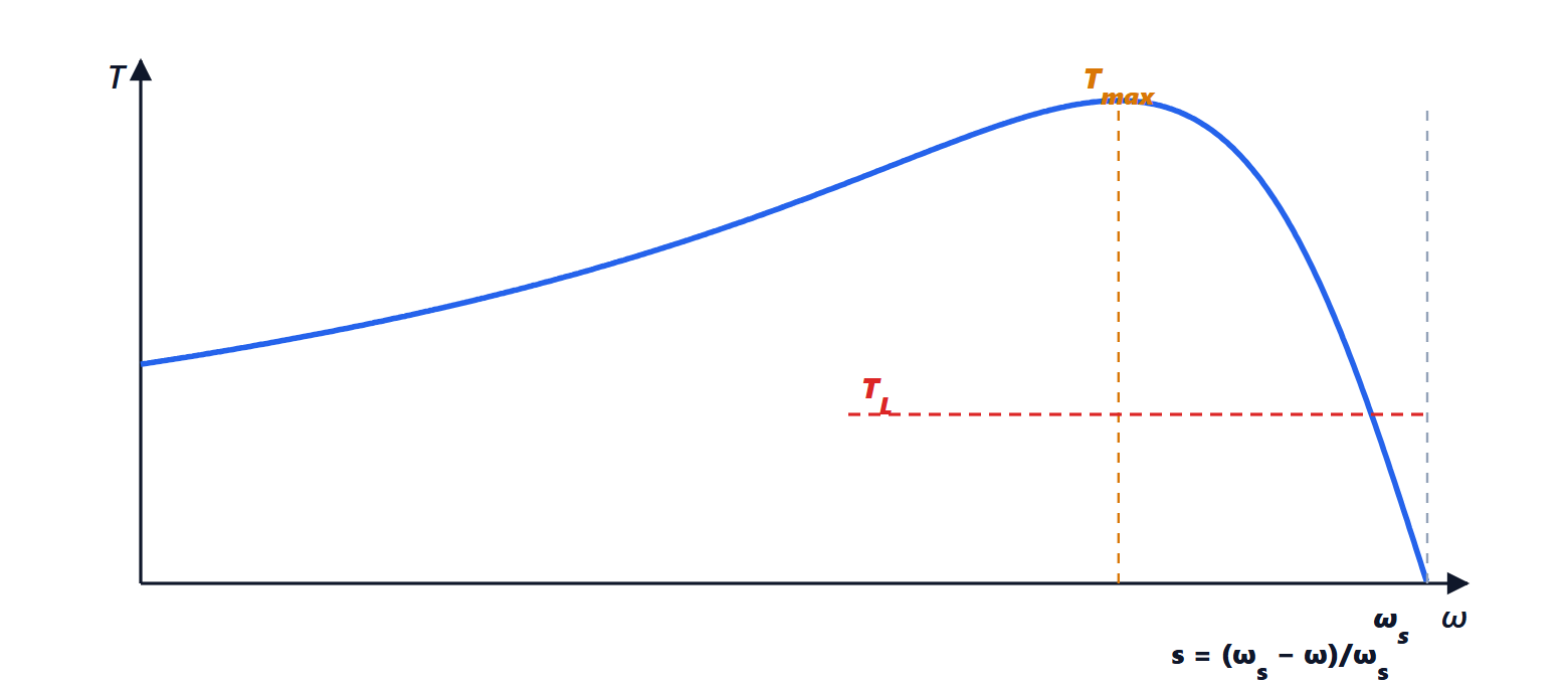
Fed directly from the mains the induction motor runs at almost fixed speed, and at start-up it draws currents 5-7 times the rated one.
Constant V/f control
With an inverter (lesson on inverters) the frequency, and therefore the synchronous speed, can be varied. But the voltage must be varied with it.
Theorem. Neglecting the stator resistive drop, to keep the motor flux constant the voltage must be proportional to the frequency.
Proof. The stator voltage equals the derivative of the flux linkage,  . For a sinusoidal flux
 one gets
 : the voltage amplitude is
 , so
 . The flux stays constant if
 , i.e.
 , is constant. ∎
Lowering the frequency without lowering the voltage the flux would grow and the iron would saturate, with enormous currents; raising it without raising the voltage the motor would weaken. With constant the torque-speed curve shifts rigidly as the frequency changes, and the motor delivers rated torque at every speed. It is the simplest control, used in pumps and fans, where regulating speed instead of throttling the flow with a valve often saves 30-50 % of the energy.
Synchronous motors and field-oriented control
In permanent-magnet synchronous motors (PMSMs, and their relatives called brushless) the rotor carries the magnets and turns exactly at the speed of the field. They have very high efficiency and power density, and they are the motors of almost all electric cars, drones and robots. To control their torque well, field-oriented control (FOC) is used.
The idea is to turn the three sinusoidal currents into two constant quantities. The Clarke transform combines the three currents into two components  on fixed axes at 90°; the Park transform brings them onto axes
 that rotate with the rotor, measured by a position sensor:

For balanced three-phase currents of amplitude  and phase
 relative to the rotor,
 and
 , and substituting one obtains
 ,
 : two constants, like the currents of a DC motor. The torque is
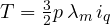 , with
 the pole pairs and
 the magnet flux: it is controlled directly by
 , while
 is kept at zero (or negative, to weaken the flux and exceed base speed). Two PI controllers on and , the inverse transforms and space-vector modulation (lesson on inverters) complete the scheme, executed by a microcontroller tens of thousands of times a second.
The result is precise, very fast torque, from zero speed to maximum. Reversing the sign of the motor brakes and becomes a generator, returning energy to the battery: this is the regenerative braking of electric cars.




