Isolated converters: flyback, forward, bridges and LLC resonant
The flyback with conversion ratio proved, leakage inductance and clamps, the forward with the duty-cycle limit proved, bridges, soft switching and LLC, the high-frequency transformer.
A mains-connected charger must galvanically separate the output from the dangerous input voltage, and must often reduce 400 V to 5 V, a ratio a buck would handle with minuscule duty cycles. Both problems are solved by inserting a transformer into the converter. Since a transformer works only with varying voltages, it is operated at the switching frequency, where it is small and light. In this lesson we look at the flyback converter with the proof of its conversion ratio, the stresses on the switch and snubbers, the forward converter with the proof of the duty-cycle limit, bridge converters and resonant converters with soft switching.
The flyback
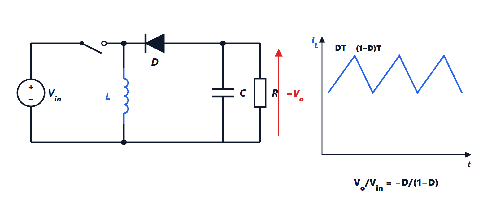
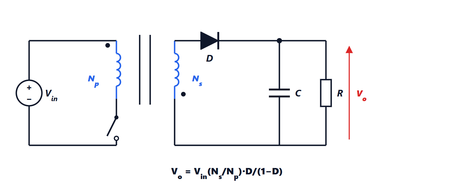
The flyback is a buck-boost (lesson on DC-DC converters) in which the inductor is replaced by two coupled windings on the same core. More than a transformer it is an inductor with two windings: it stores energy during the on-time and releases it during the off-time.
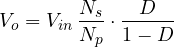
Theorem. In continuous conduction the flyback has
Proof. Apply volt-second balance to the magnetising inductance seen from the primary. During the on-time the primary sees  . During the off-time the secondary conducts and imposes
 across itself (neglecting the diode); referred to the primary through the turns ratio, it is a voltage of opposite sign and value
 . The balance gives
 , which yields the formula. ∎
The turns ratio makes low outputs possible with reasonable duty cycles: from 325 V (rectified mains) to 5 V with  requires
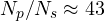 . With one magnetic component, one switch and one diode, the flyback is the simplest and cheapest converter up to about a hundred watts: it is the one in almost every charger and auxiliary supply. With several secondaries it gives several isolated outputs.
Stresses. At turn-off the switch must withstand  , plus a spike due to the leakage inductance, the part of the primary’s flux not linked with the secondary: the energy stored in it cannot pass to the output and, without precautions, would destroy the switch. A clamp circuit (or RCD snubber) is added to absorb that energy, or an active circuit that recovers it.
The forward
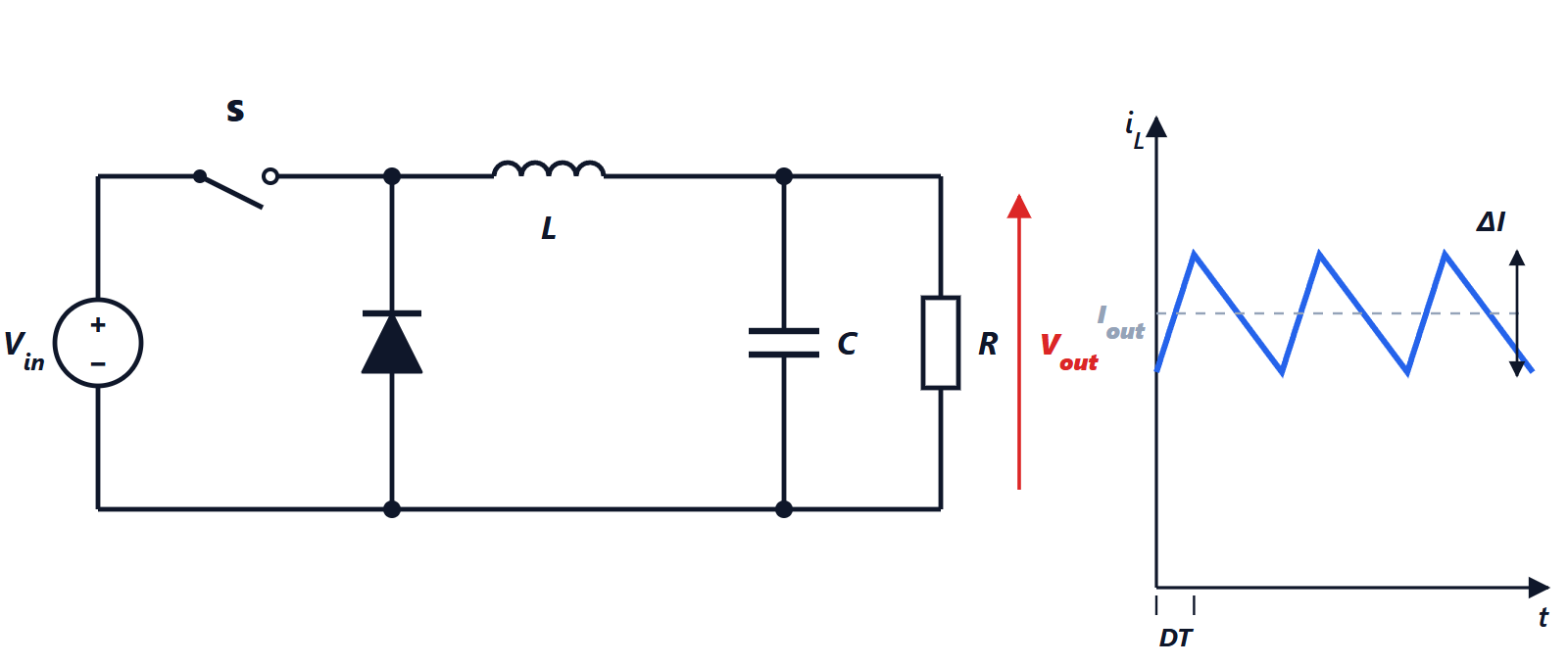
The forward is a buck with a real transformer, which transfers energy during the on-time:  . It has a separate output inductor and a second freewheeling diode, and it suits powers from 100 W to a few hundred. The problem is that the transformer core, magnetised during the on-time, must be reset during the off-time, otherwise the flux grows every period until saturation. The classic way is a third reset winding with a diode, which returns the energy to the input.
Theorem. With a reset winding with the same number of turns as the primary, the forward converter’s duty cycle cannot exceed 0.5.
Proof. During the on-time the primary sees for a time  . During reset the auxiliary winding, with the same turns, imposes
 . By volt-second balance on the magnetising inductance the reset time must equal the on-time, , and it must fit within the off-time:
 , i.e.
 . ∎
Bridge converters
Above a kilowatt (server supplies, electric car chargers, welders) half-bridge and full-bridge converters are used: the transformer primary is driven alternately in both directions, the core is used in both flux directions (so it is smaller and resets by itself), and the secondary is rectified and filtered. The phase-shifted full bridge regulates the output by varying the phase shift between the two legs instead of the duty cycle.
Soft switching
Switching losses (lesson on devices) arise because voltage and current overlap during transitions. If the switch is made to turn on when the voltage across it is already zero (ZVS, zero voltage switching) or to turn off when the current is zero (ZCS), switching losses almost disappear. This is achieved with resonant circuits: the most widespread is the LLC converter, with an inductor, a capacitor and the transformer’s magnetising inductance forming a resonant circuit. The converter regulates the output by varying the frequency around resonance, and with reduced switching losses it works at hundreds of kilohertz with efficiencies above 97 %. It is the solution of high-efficiency supplies for data centres and televisions.
The high-frequency transformer
The voltage induced in a winding is  : for a given voltage, the product of the number of turns, the core cross-section and the change of field is fixed by the time the voltage is applied. At higher frequency fewer turns or a smaller core are needed: at 100 kHz a 100 W transformer fits in a few cubic centimetres, while at 50 Hz one weighing a kilogram would be needed. The core is made of ferrite, which has low losses at high frequencies, and the windings are made so as to reduce leakage and skin-effect losses (lesson on magnetic components).