Superposition, Thevenin and Norton theorems, maximum power transfer
The superposition principle, Thevenin's theorem with proof, Norton, maximum power transfer with proof, equivalents and measurements.
Network theorems let you simplify a circuit without writing all its equations. The most important, Thevenin’s theorem, says that any linear network, however complicated, seen from two terminals behaves like a source with a resistance in series. It is how an engineer thinks about a power supply, a sensor, an amplifier’s output. In this lesson we cover superposition, the Thevenin and Norton theorems and maximum power transfer.
Superposition
In a linear circuit with several independent sources, every voltage and current is the sum of the contributions of each source taken alone, with the others switched off:
- a voltage source switched off becomes a short circuit (
 );
- a current source switched off becomes an open circuit (
 ).
The reason is that the circuit’s equations are linear, and the solution of a linear system depends linearly on its right-hand side. Careful: superposition holds for voltages and currents, not for powers, which are quadratic.
Example. In the circuit of the nodal analysis lesson the contribution of  to
 and that of
 can be computed separately and added: you get back
 V. It is also the way to reason about circuits with several signals: the DC and AC parts of a voltage are analysed separately.
Thevenin’s theorem
Any linear network seen from two terminals A and B is equivalent to an ideal voltage source  in series with a resistance
 .
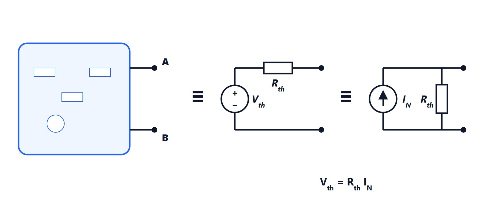
How to compute them:
- is the open-circuit voltage: the voltage between A and B with the terminals open;
- is the resistance seen from A and B with every independent source switched off. If there are dependent sources, apply a test source to the terminals and compute the ratio of voltage to current.
Proof
Connect to the terminals a test current source that draws the current  from the network, leaving through terminal A, and compute the voltage
 between A and B. By superposition is the sum of two contributions. The first is that of the internal sources with the test source switched off, that is with the terminals open: it is the open-circuit voltage . The second is that of the test source alone, with the internal sources switched off: the network becomes a resistance from which the current is drawn, and
 appears across it. So
 , exactly the relation of a real voltage source.
Example. A divider with  V,
 kΩ,
 kΩ, seen across
 :
 V,
 kΩ. Connecting a 2.67 kΩ load the voltage drops to 2 V, half: the reason a divider works only with loads much larger than .
Norton’s theorem
It is the dual: the same network is equivalent to an ideal current source  in parallel with , where is the short-circuit current between A and B. The two forms are linked by
 , which is also a handy way to find : the ratio of open-circuit voltage to short-circuit current. In the lab this is exactly how it is done, with two measurements, when the inside of the network is unknown.
Maximum power transfer
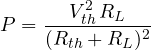
A source with internal resistance feeds a load  . The power in the load is
Proof
Differentiating with respect to and setting it to zero:

and the maximum power is 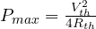 .
Watch the efficiency. With  half the power goes to the load and half is dissipated in the internal resistance: 50% efficiency. That is why matching is used where it matters to extract the most from a weak source (an antenna, a microphone, a solar panel with a maximum power point tracker), never in power distribution, where high efficiency is wanted and so
 .
Equivalents and measurements
The Thevenin and Norton theorems explain many practical facts: why a voltmeter must have a high internal resistance (so as not to load the circuit, it must be much larger than the seen from the measuring point), why an ammeter must have a low one, why a power supply’s voltage drops under load ( is its output resistance), and why sensor and amplifier datasheets always give the output impedance.




