Threads and threaded fasteners: designation and representation
The ISO metric thread with a table of pitches and tap drills, designation, conventional representation of screws and tapped holes, screws, bolts and studs, property classes.
Screws, bolts and studs are the most common fasteners: a car contains thousands of them, a computer a few dozen. Drawing the helix of every thread would be very long and pointless, so the standards provide a simplified conventional representation (ISO 6410) and a designation that, in a few letters, says everything needed.
The ISO metric thread
A thread is a helical ridge wound on a cylinder (screw, external thread) or inside a hole (nut or tapped hole, internal thread). The most widely used is the ISO metric thread, with a 60° triangular profile. The main quantities:
- nominal diameter
 : the outside diameter of the screw, at the crests;
- minor diameter: the diameter at the roots of the screw thread;
- pitch
 : the distance between two adjacent crests, that is how far the screw advances in one turn (for single-start threads).
The minor diameter of the internal thread is  . Before tapping, in practice, a drill of diameter about
 is used.
| Designation | Coarse pitch (mm) | Tap drill (mm) |
|---|---|---|
| M3 | 0.5 | 2.5 |
| M4 | 0.7 | 3.3 |
| M5 | 0.8 | 4.2 |
| M6 | 1 | 5 |
| M8 | 1.25 | 6.8 |
| M10 | 1.5 | 8.5 |
| M12 | 1.75 | 10.2 |
| M20 | 2.5 | 17.5 |
Designation
- M10: metric thread, 10 mm diameter, coarse pitch (1.5 mm). The coarse pitch is not written.
- M10 × 1.25: fine pitch, always written. A fine pitch resists vibration better and allows finer adjustment.
- M10 – 6H / M10 – 6g: with the tolerance class of the internal or external thread.
- LH: left-hand thread, which screws in anticlockwise (the left bicycle pedal, fuel gas cylinders).
There are also non-metric threads: G (parallel pipe thread, for pipes and hydraulic fittings), Tr (trapezoidal, for lead screws and vices), and the inch threads UNC/UNF used in the United States. SMA radio-frequency connectors, for example, use a 1/4-36 UNS inch thread.
Conventional representation
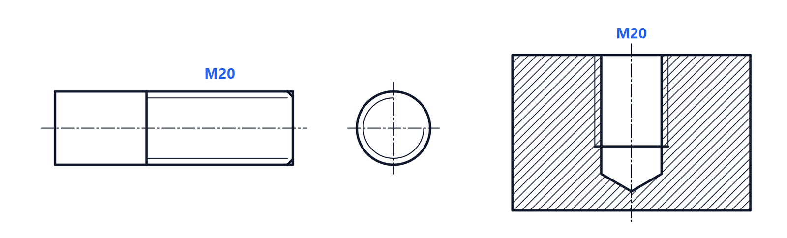
The rule to remember: draw with a wide line what you can see and touch (the crests of the screw, the drilled hole of the internal thread), with a narrow line the thread roots.
- Screw in view: outside diameter with a wide line, minor diameter with a narrow line. The end of the threaded length is a wide transverse line. In the end view the outer circle is wide and the root circle is a narrow arc of about three quarters of a turn, open at any point.
- Internal thread in section: the hole (minor diameter) with a wide line, the nominal diameter with a narrow line. The hatching goes right up to the wide line, that is to the hole, because there is material there. The bottom of a blind hole has the 120° conical point left by the drill, beyond the threaded part.
- Screw fitted into an internal thread, in section: the screw covers the internal thread. Where they engage the screw is drawn: its wide crests coincide with the narrow nominal diameter of the internal thread.
Hidden threads are drawn dashed only when essential.
Threaded fasteners
- Screw: screws directly into a tapped hole in the part.
- Bolt: screw plus nut, passing through clearance holes in the parts. The clearance hole is a little larger than the screw (for M10, 10.5 to 11 mm) to absorb position tolerances.
- Stud: a bar threaded at both ends, screwed permanently into one part; the second part is held with a nut. It is used when parts are often dismantled, so as not to wear the thread in the main part, for example on engine cylinder heads.
- Washers: spread the load under the head and the nut.
The most common heads are hexagon (tightened with a spanner), socket head cap (hex key, when there is little room at the side) and countersunk (flush with the surface, in a 90° conical countersink).
How far a screw must engage
In a tapped hole in steel an engagement length of about one diameter is enough; in cast iron about 1.5 diameters, in aluminium and light alloys about 2, because the material of the internal thread is weaker than the screw. Plastic housings of electronic devices often use brass threaded inserts, heat-set into the plastic, so that repeated disassembly does not strip the thread.
Property class
The property class is stamped on the head of steel screws, for example 8.8. The first number times 100 gives the tensile strength in MPa (800 MPa); the product of the two numbers times 10 gives the yield strength (8 × 8 × 10 = 640 MPa). The most common classes are 4.6, 8.8, 10.9 and 12.9. Stainless screws use a different designation, such as A2-70: austenitic steel A2 with 700 MPa tensile strength.
Locking methods
Vibration can loosen a threaded joint. It is prevented with spring or toothed washers, nylon-insert lock nuts, lock nuts, anaerobic threadlockers (screw “glues”) or safety wire in aerospace applications. The most reliable method, though, is still to apply the correct tightening torque with a torque wrench: it is the screw’s preload that holds the joint together.