Dimensioning: rules, symbols and dimensioning systems
Elements of a dimension, diameter, radius and chamfer symbols, basic rules, chain, parallel and coordinate dimensioning, functional dimensioning and common mistakes.
The views give the shape of the part, the dimensions give its size. A drawing without dimensions cannot be made: you never measure on the sheet, because paper deforms, printing changes the scale and the drawing may not be exact. In the workshop only what is written is read. Dimensioning is governed by ISO 129-1.
The elements of a dimension
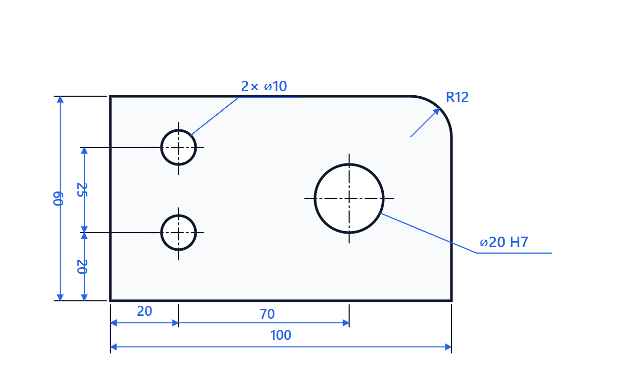
- Extension lines: continuous narrow lines extending the edges of the part. They start with a small gap from the outline and run about 2 mm past the dimension line.
- Dimension line: continuous narrow, parallel to the size being dimensioned.
- Terminators: closed filled arrowheads, or oblique strokes at 45° (used in architecture). A drawing uses one type only.
- Dimension value: in millimetres, without writing the unit, above the dimension line and readable from the bottom or the right of the sheet.
Dimensions are preferably placed outside the outline of the part, on the view that best shows the feature, and hidden edges are not dimensioned.
Symbols
| Symbol | Meaning | Example |
|---|---|---|
| ⌀ | diameter | ⌀20 |
| R | radius | R12 |
| □ | side of a square | □16 |
| S⌀, SR | diameter or radius of a sphere | S⌀30 |
| × 45° | chamfer | 2 × 45° |
| n × | repeated equal features | 4 × ⌀8 |
A radius is dimensioned with a single arrow, starting from the centre (or along its direction) and touching the arc. A diameter can be dimensioned on a view where the circle is not seen, for example on the side view of a shaft: the ⌀ symbol is enough to say it is round, and often saves a view.
The basic rules
- Each dimension is given only once. Repeating it on two views risks contradictory values after a change.
- All the necessary dimensions, none too many. If the part is 100 wide and two lengths of 30 and 70 are given, the overall dimension is redundant: leave it out, or show it in brackets as an auxiliary dimension, (100).
- Avoid crossing dimension lines and extension lines where possible. Shorter dimensions go closer to the part, longer ones further out.
- Centre lines and outlines are not used as dimension lines, but they can act as extension lines.
- The dimensions of a feature (for example a hole) are grouped on the view where the feature is seen best.
Dimensioning systems
- Chain: each dimension starts where the previous one ends. It is simple but errors add up: with five dimensions each toleranced ±0.1 mm, the position of the last feature can be off by ±0.5 mm.
- Parallel: all dimensions start from the same datum (an edge, an axis, a hole). Errors do not build up, because every feature is referred directly to the datum. It is the system used in the figure, from the left and bottom edges.
- Running: equivalent to parallel but more compact: a single dimension line with the origin marked by a dot and the values written at each feature.
- Coordinate: a table gives the
 coordinates of each hole from an origin. It is the natural format for CNC machines and for drilling printed circuit boards.
Functional dimensioning
Which dimensions to write is not a neutral choice: it should be made thinking about how the part works and how it will be machined and inspected. Dimensions that matter for function, those that mate with other parts, are given directly, starting from the datum surfaces the part uses in the assembly.
Example. On a front panel, the distance between the two fixing holes of a connector must match that of the connector. It should be dimensioned directly between the two holes, not as the difference of two dimensions from the edge of the panel: in that case the tolerances of the two dimensions would add up exactly on the most critical size.
Common mistakes
- Dimensioning to a hidden edge instead of on the view where the feature is visible.
- Placing a dimension inside hatching without interrupting it, or on top of a drawing line.
- Forgetting the position dimensions of holes: a hole needs its diameter and two dimensions locating its centre.
- Chain-dimensioning sizes that must be accurate relative to a datum.
- Leaving “calculable” dimensions to the reader: if the workshop has to do a subtraction to find a size, sooner or later they get it wrong.